V. liquid tube strainer, V. care and maintenance, A. motor – Bryant FA4A User Manual
Page 23: Utc tech pub, Device
Attention! The text in this document has been recognized automatically. To view the original document, you can use the "Original mode".
A U G / 1 4 / 2 0 0 8 / T H D 0 3 : 5 0
UTC TECH PUB
F A X N o . 3 1 7 2 4 0 5 6 6 2
P . 0 2 3
n
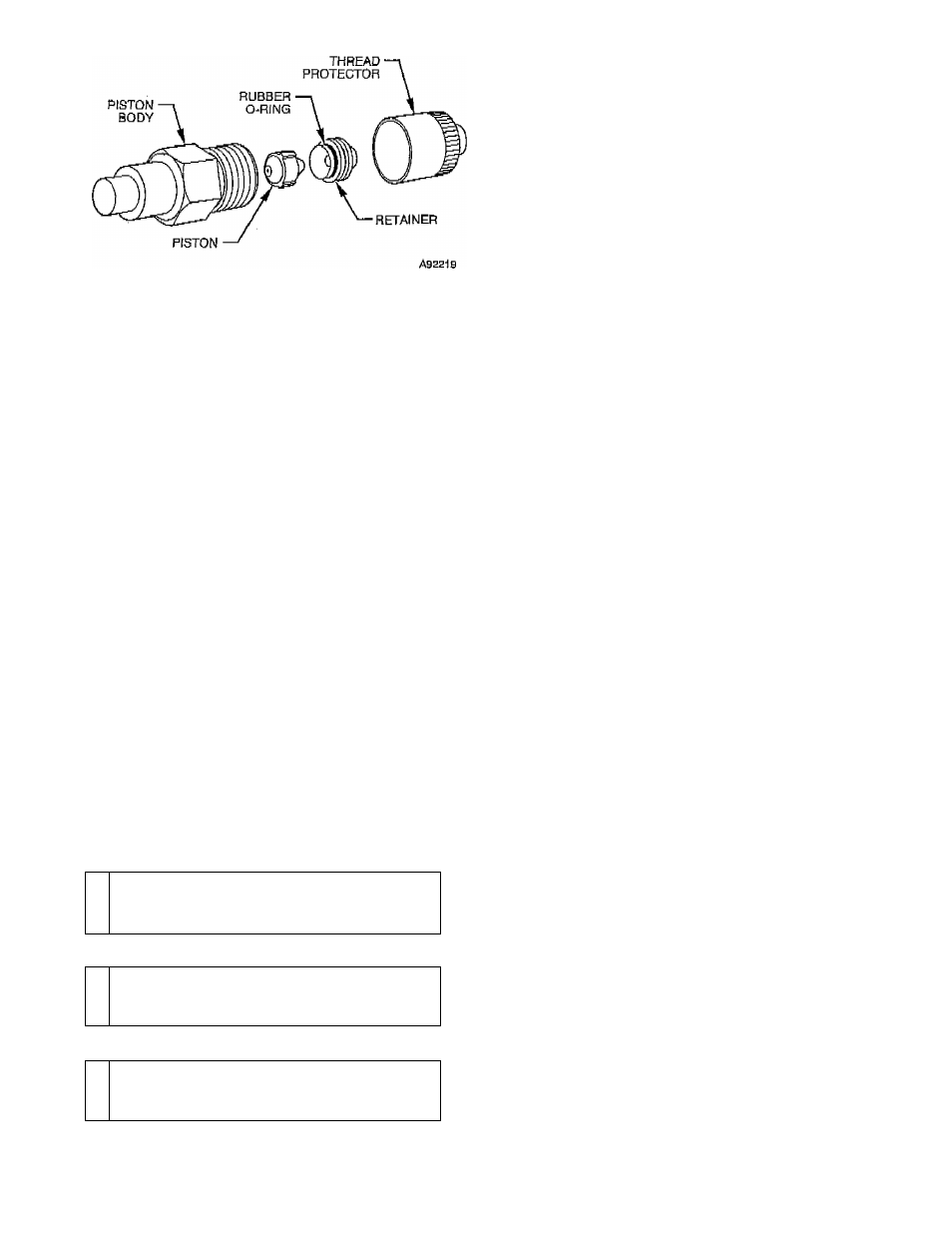
Fig, 19—Refrigerant Flow-Control Device
(For FD3A and FG3A)
A
CAUTION:
Use a backup wrench and do not over
tighten as deformation of refrigerant flow-control device
body will occur, causing piston to lodge in a partially
Open Or
closed position.
6. Install new or cleaned piston in refrigerant flow-control
device body.
7. Install new retainer (because of probable damage which
occurred in initial remov&J)-
8. Reconnect refrigerant tube to refrigerant flow-cOntroI de
vice.
9. Pressurize tubing and coil, then leak-check.
10. Evacuate tubing and cojl as necessary.
)V. LIQUID TUBE STRAINER
The refrigerant flow-coittrol device .is.
protected
on indoor coil by
a wire mesh strainer. If strainer becomes plugged:
1. Complete items 1 and 2 under Cleaning or Replacing
Refrigerant Flow-Control Device section.
2.
Loosen flare fitting joint connecting refrigerant flow-
control device to coil liquid refrigerant tube.
3. Remove sheet metal screw holding bracket clip in place,
Screw is located between coil and refrigerant flow-control
device,
4. Pull bracket clip out.
5. Remove refrigerant flow-control device assembly,
6. Pull strainer out of coil liquid refrigerant tube and replace
with new strainer,
V. CARE AND MAINTENANCE
A
WARNING:
Hinged access panel contains electrical
components and is heavy. Support panel when lowering
to clean unit to avoid personal injury.
A
WARNING:
Disconnect electrical power to all circuits
before servicing unit. Failure to do so may result in
personal injury from electrical shock ox movingiparts.
A
WARNING:
As with any mechanical equipment, per
sonal injuXy can result from sharp metal edges. Be careful
when removing parts.
The minimum maintenance requirements for this equipment arc as
follows:
1. Inspect and dean or replace field-supplied air filter each
month or as
required.
2. Inspect cooling coil, drain pan, and condensate drain each
cooling season for cleanliness. Clean as necessary. (To be
performed by trained personnel.)
3.
Inspect blower motor and wheel for cleanliness each
heating and cooling season. Clean as necessary,
4. Inspect electrical connections for tightness and controls for
proper operation each heating and cooling season. Service
as necessary,
NOTE:
Never operate without a Alter or with hinged access door
Open,
Damage to blower motor may result.
A. Cooling Coll, Drain
Pan,
and Condeneata
Drain
Remember to disconnect electrical power before opening hinged
access panel.
The cooling coil ig easily cleaned when dry. Inspect coil and clean
(if necessary) before e&ch cooling season. If coil inlet face is
coated with dirt or lint, vacuum with a soft brush attachment.
Be careful not to bend coil flns. If coil is coated with oil or grease,
clean it with a mild detergent-and-hot water solution. Rinse coil
with olear water. Be careful not to splash water onto insulation.
Inspectidrain pan and condensate drain at same time cooling coil
is checked. Clean drain pan and condensate drain by removing any
foreign matter from pan. Fliish pan and drain tube with dear water.
Clear drain line ifrresfricted.
NOTE:
There MUST be a trap in condensate line. Trap must be
at least 3-in. deep, not higher than the bottom of unit condensate
drain opening, and pitched downward to an open drain or sump.
B. Blower Motor and Wheel
Clean blower motor and wheel when cooling coil is deaned.
Lubricate , motor every 5 years if motor is used on-intermittent
opefafidn (thermostat FAN switch at AUTO position);, or every 2
years if motor is in continuous operation (thermostat FAN switch
at ON position). Remove motor to lubricate. Put approximately 8
drops of SÁE 10 nondetergent oil in each oil hole. Do not bveroil
motor. Plug hole securely so that oil does not drip when hinged
access panel is lowered'to 'open position.
Blower motor and wheel may be cleaned using a vacuum with a
soft brush attachment. Remove grtaae with a mild solvent such as
hot water and detergent. Be careful not to disturb balance weights
(dips) on blower
wheel
vanes. Do not drop or bend wheel as
balance will be affeefed.
FG3A
service
and
TROUBLESHOOTING
1. SERVICE
A. Motor
......................
Ball bearing oilers are provided on blower motor. Use electric
motor oil 6r SAE
lp
or'20 nondetergent oil. Check motor mount
bracket and''Í3ás¿ bolte. Tighten as required.
B. Blower
Check ball bearings for wear. Ball bearings are self-aligning and
grease packed. Replace as required. Check thrust collars for end
play and alignment of wheel. Check blades for accumulation of.
dirt.
Clean as
required.
Check mounting brackets, base bolts, and
isolation material.
See Fig, 20 for diagram of internal wiring for blower coil
assembly. Control box (standard 4-in. junction box) is mounted on
refrigerant connection side of unit. All leads pass through strain
relief where they
enter
Control box. Wiring inside cabinet is
located so it does not come in contact with moving parts or sharp
edges,
C. Pulley and Belts
Check beJt tension and pulley alignment. (See Fig, 21,) Belt
tension is adjusted by motor tailpiece bolt, A deflection of about
3/4 in. to 1 in, per foot of span should be obtained by pressing belt
-
23
-