Instalung blade guard – Sears 113.241591 User Manual
Page 23
Attention! The text in this document has been recognized automatically. To view the original document, you can use the "Original mode".
3.
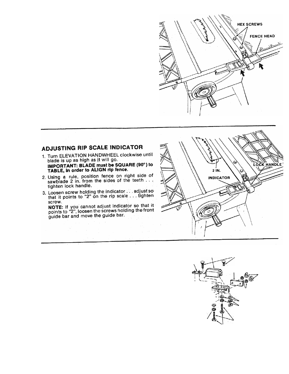
The rip fence must be PARALLEL with the
sawblade and miter Gauge grooves . . . Move
fence until it is along side of groove. Do NOT
LOCK IT. It should be parallel to groove. If it is
not;
A. Loosen the two “Hex Head Screws.”
B. Hold fence head tightly against bar......... move end
of fence so that it is parallel with groove.
C. Alternately tighten the screws.
INSTALUNG BLADE GUARD
1. From Among the loose parts find:
4
Truss Head Screws
1/4-20
x
3/4
in. long
2
Hex Socket Setscrews
1/4-20
x
1
in. long
4
Washers
17/64 X 5/8 X 1/32
6 Lockwashers
1/4
in. External Type
(approx, dia. of hole 1/4 in.)
2 Hex Head Nuts 1/4-20
(approx, dia. of hole 1/4 in.)
2 Wing Nuts 1/4-20
(aprox. dia. of hole 1/4 In.)
1
Spreader Support
1
Rate Nut .........
1 Spreader Clamp ......................
1 Spreader Bracket
SPREADER SUPPORT
PLATE
'
NUT
TRUSS HEAD SCREW
3/4 IN. LONG
J SPREADER CLAMP
TRUSS HEAD SCREW
3/4 !N. LONG
FLAT WASHER
17/64 IN. HOLE
LOCkWASHEH
^
EXT. 1/4 IN.
HEX NUT
FLAT WASHER '
1T/S4IN.HOLE
LOCKWASHER
EXT. 1/4 IN.
WING NUT
LOCKWASHER
EXT. 1/4 IN.
FLAT WASHER
17/64 IN. HOLE
LOCKWASHER
EXT. 1/4 IN.
HEX NUT
SOCKET HEAD SETSCREW
1 IN. LONG
HEX NUT
2S