Mounting the flexible shaft, Mounting the flexible, Shaft – Sears 113.241591 User Manual
Page 15
Attention! The text in this document has been recognized automatically. To view the original document, you can use the "Original mode".
THESE TWO EDGES EVEN
5. From among the loose parts, find the following
hardware:
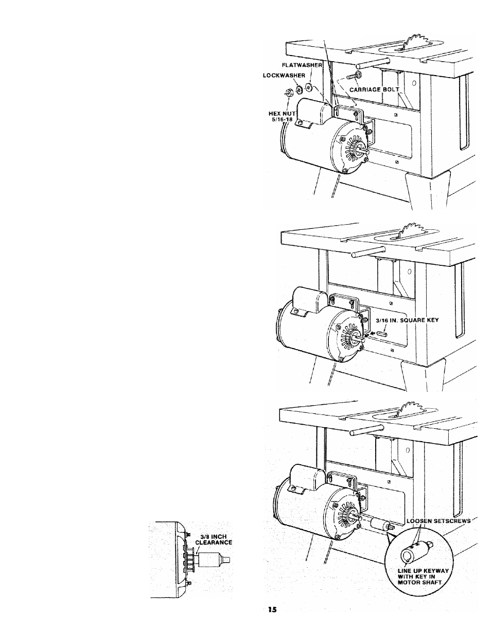
4 Carriage Bolts, 5/16 - 18 x 3/4 in. long
4 Flatwashers 17/64 x 3/4 x 1/16
4 Hex. Nuts. 5/16 - 18 (approx, dia, of hole 5/16
in.)
4 Lockwashers, 5/16 in. External Type
(approx, dia. of hole 5/16 in.)
6. Place motor on MOTOR MOUNT . .. insert bolts
through holes in MOUNT then through the motor.
Install lockwashers, and hex. nuts. Do not
tighten,
7. Position MOTOR BASE on MOTOR MOUNT so
the edges of the MOTOR BASE and the MOTOR
MOUNT are even. Tighten all 4 Hex. nuts
securely.
MOUNTING THE FLEXIBLE SHAFT
1. From among the loose parts find the following:
3 Pan Head Screws 8-32 x 3/8 in. long
3 Lockwashers External Type No. 8
2 Carriage Bolts 1/4 - 20 X 3/4 in. long
2 Hex Head Screws 1/4-20 x 1 in. long
4 Hex Nuts 1/4-20 (approx, dia. of hole 1/4 in.)
2 Washers 17/64 x 3/4 x 1/16
4 Lockwashers External Type 1/4 in. (approx,
dia. of hole 1/4 in.)
2 Shaft Brackets
1
Flexible Shaft Assembly
1 Motor Connector
1 Square Key 3/16 x 5/8 long
2. install 3/16 in, square key in motor shaft keyway.
3
Loosen the 2 setscrews in the MOTOR
CONNECTOR. Line up the keyway in MOTOR
CONNECTOR with the 3/16 in. square key on
the motor shaft.
4. Slide the MOTOR CONNECTOR ontothe motor
shaft as far as it wilt go. SECURELY tighten 2
setscrews. Test setscrews by trying to slide
motor connector off motor shaft.
IMPORTANT:
Make
sure
the
MOTOR
CONNECTOR is pushed on the shaft as far as it
will go, (Approx. 3/8 inch from motor end
shield.) .....