Sears 113.241591 User Manual
Page 17
Attention! The text in this document has been recognized automatically. To view the original document, you can use the "Original mode".
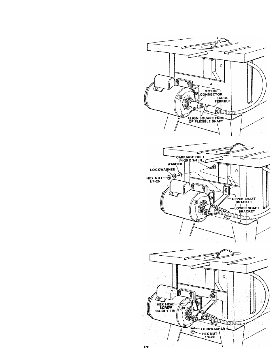
9. Bend the SHAFT HOUSING toward the motor
as illustrated. Insert end of LARGE FERRULE
over
MOTOR
CONNECTOR
and
line
up
SQUARE END of flexible shaft with square hole
in MOTOR CONNECTOR.
NOTE: If FLEXIBLE SHAFT is not properly
positioned in the square hole of the MOTOR
CONNECTOR it will not be possible to make
this con nection. It may be necessary to carefully
rotate the blade to line up the SQUARE END of
the flexible shaft with the square hole in the
MOTOR CONNECTOR.
10. Push LARGE FERRULE as far as it will go
against the motor end cap. If it does not enter
motor end cap to ferrule bead, rotate saw blade
while pushing ferrule toward motortopermitthe
square ends of the core to enter their square
mating holes deep enough to allow ferrule to be
correctly positioned.
CAHEFULS-V ROTATE BLADE B¥
HAND TO LINE UP SQUARE
END OF FLEXIBLE SHAFT
WITH SQUARE HOLE IN
MOTOR CONNECTOR
11 Assemble upper and lower shaft bracket by
inserting 1/4-20x3/4 carriage bolts in upper and
lower square holes on the saw base rear panel
and then through the slotted hole in the shaft
brackets. Assemble 17/64 x 3/4 x 1/16 washer,
External Type Lockwasher, and 1/4-20 Hex Nut.
Finger tighten.
12. Position the upper and lo^^r
they wrap around the LARGE FERRULE on the
SHAFT HOUSING. Bottom^bracket Should ¡ust
contact and support
LARGE FERRULE. Tighten
nutsthat
hold theshaftbracketstothesaw base-
13. Assemble two 1/4-20 x 1
External Lockwashers, and lM-20 Hex Nuts to
clamp upper and lower brackets together. Do*
not tighten.