Repair & adjustment – Sears 917.25446 User Manual
Page 22
Attention! The text in this document has been recognized automatically. To view the original document, you can use the "Original mode".
REPAIR & ADJUSTMENT
FIGURE 35
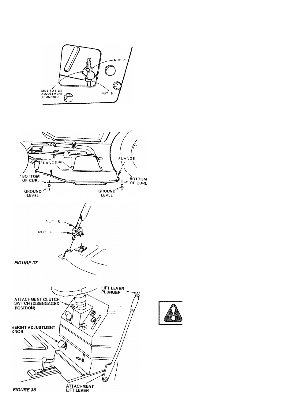
FIGURE 36
Sid
0
-to-Skie mower Adjustment
a Depress lift lever plunger and use lift lever to raise
mower to maximum cutting height (Fig. 34)
•b Measure height from bottom of curt to ground level at
front of mower. Distance "A
"
should be the same (Fk)
34).
c If distance
"
needs to be changed, snap out access
hole cover on LH. side above footrest Use 11/16"
wrench on nuts "8" and "C" at side-to-side adjustment
trunnion (Fig 35).
d To raise left side of mower, toosennut "B" and tighten nut
"C"
e To bwer left side of mower, loosen nut "C" and tighten
nut "B"
NOTE: ONE ROTATION OF ADJUSTMENT NUTS IS
EQUIVALENT
TO
APPROXIMATELY
5
MM
{3/16")
HEIGHT CHANGE
f Be sure all nuts are securely tightened.
FronFTo^Rear Mower Adjustment
a. To obtain the best cutting results, your mower housing
should be adjusted so the front and rear flange distance
"D" (Fig. 36) is 13 mm (1/2") lower in front when the
mower is positioned in the highest cutting position.
NOTE:
MEASURE
DISTANCE
"D"
FROM
GROUND
LEVELTO BOTTOM OFCURLON RIGHT REAR FLANGE
AND COMPARE TO DISTANCE "D" AT RIGHT FRONT
FLANGE
b To raise rear of mower, loosen nut "E" on both rear
suspenston arms Screw both nuts "F" up an EQUAL
NUMBER OF TURNS (Fig. 41)
c When distance "D" is 13 mm (1/2") lower at front than
rear, tighten nuts "E".
d To tower rear of mower, loosen nut "F" on both rest
suspension arms an EQUAL NUMBER OF TURNS (Fig
37).
e. When distance "D" is 13 mm (1/2") lower at front than
rear, retighten nuts "E"
NOTE: \A/HEN ADJUSTING REAR SUSPENSION TRUN
NIONS, ALWAYS ADJUST BOTH EQUALLY SO MOWER
WILL STAY LEVEL
Mower Drive Belt Removal
NOTE:
MOWER
BELT
INSTALLATION
DECAL
LO
CATED ON MOWER HOUSING
REPLACE ONLY WITH THE BELTS
SPECIFIED IN THIS MANUAL.
a
Place attachment clutch switch in "Disengaged" posi
tion (Fig. 38).
b Turn height adjustment knob to its lowest position.
Move attachment lift lever (Fig. 38) forward to lower
mower to its hwest position
c.
Roll belt off engine pulley (Fig.. 39)
d. Pull belt off both mower pulley and idler pulleys (Fig. 40}
e.
To replace mower drive belt, reverse above proce
dure.
NOTE: MAKE SURE DRIVE BELT IS ENGAGED IN
22
all
PULLEYS