Assembly – Sears 917.25446 User Manual
Page 10
Attention! The text in this document has been recognized automatically. To view the original document, you can use the "Original mode".
ASSEMBLY
FIGURE 10
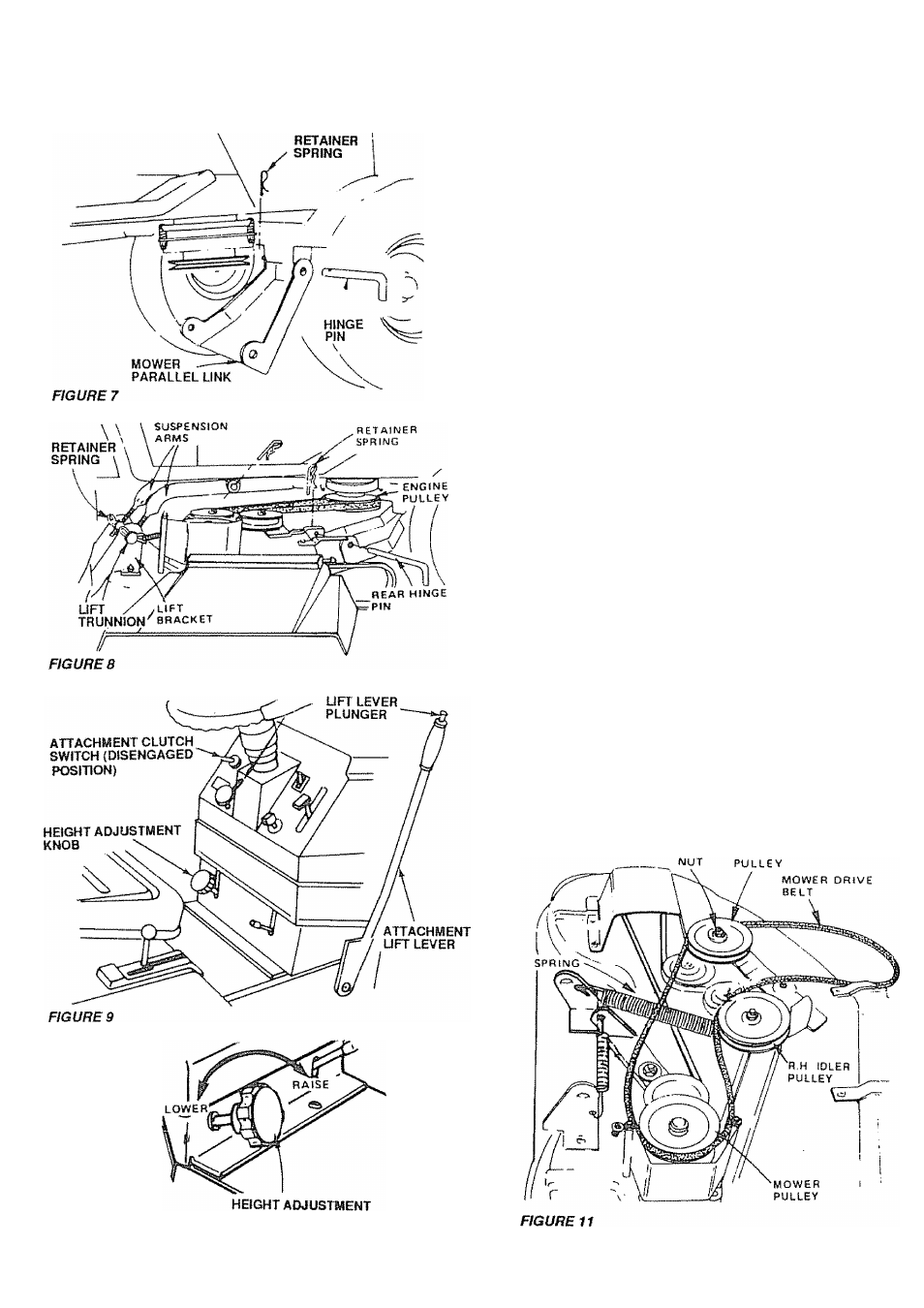
ff. Mower ana Drive Belt Installation
INSTALL MOWER PARALLEL LINK
Your tractor has been shipped with the mower parallel link
included in the parts carton. Install mower parallel link on
tractor (Fig. 7) using hinge pin and retainer spring
NOTE: SMALLER END OF PARALLEL LINK MOUNTS
TO TRACTOR. USE THE SHORTEST HINGE PIN FOR
MOUNTING
INSTALL MOWER
Your mower installs without the use of tools.
a.
Raise attachement lift lever (Fig 9) to its highest posi
tion.
b Turn height adjustment knob counterclockwise I
to lowest position (Fig 10)
a Slide mower under tractor with discharge guard to R. H
side.
d Install rear hinge pin through mower lift brackets and
parallel link (Fig. 8). Secure with retainer spring.
0
Move attachment lift lever (Fig. 9) forward to hwer
suspension arms. Remove retainer springs from lift
trunnions (Fig. 8).
f Slide trunnions through upper lift bracket holes and
secure with retainer springs (Fig. 8}..
g.
Pull LH idler pulley (Fig. 12) toward the right hand side
of the tractor and roll belt over engine pulley (Fig. 8)
NOTE: MOWER DRIVE BELT INSTALLATION DECAL
LOCATED ON MOWER HOUSING
h.
Use attachment lift lever (Fig 9) to raise mower.
1
Turn height adjustment knob clockwise (7~\) to the
middle of its travel (Fig 10).
7. Check Cutting Level
The blade housing was set at the factory to cut level After mowing
a short distance, took at the area that was cut. If the blade housing
cuts uneven, see "MOWER ADJUSTMENT."page 21
8. Final Assembly
Make sure all fasteners are tight.
Read and follow the operation instructions (page 11).
Know the location and purpose of all controls.
Check oil and gasoline (page 12) before starting the
tractor.
L.H IDLER
a.
b.
c.
KNOB
10