Carrier 38CQ User Manual
Page 8
Attention! The text in this document has been recognized automatically. To view the original document, you can use the "Original mode".
COOLING CYCLE CHARGING CHART
METHOD
1. Operate unit a minimum of 10 minutes before
checking
charge,
and
after
each
charge
adjustment.
2. Measure suction pressure by attaching a gage to
outdoor unit suction valve service port. (See
Fig. 32 for correct service port location on
cooling cycle.)
3. Measure outdoor (coil inlet) air dry-bulb tem
perature with service thermometer.
4. Using a sling psychrometer, measure wet-bulb
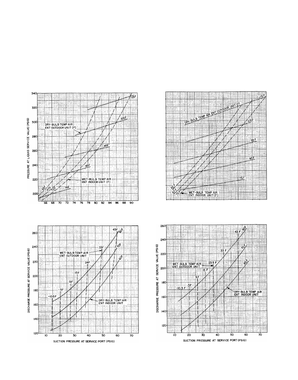
PRESSURE AT SUCTION SERVICE VALVE (PSIG)
Fig. 9 — 38CQ015 with 40AQ018 Cooling Cycle
Charging Chart (R-22)
temperature of air entering indoor unit.
5.
Refer to correct Charging Chart. Locate on
curves where outdoor air dry-bulb and indoor
air wet-bulb temperature lines intersect.
6. From intersect point, project vertically down
ward to chart suction pressure line. Compare
chart suction pressure to unit suction pressure
(Step 2).
7. If unit suction pressure is lower than chart
pressure, add refrigerant to system until chart
pressure is reached. If unit suction pressure is
higher than chart pressure, remove refrigerant
until chart pressure is reached.
340
320
300
3
5
ui
£ 280
o 260
cr 240
220
20 O'
66
68
70
72
74
76
78
80
82
84
86
88
90
PRESSURE AT SUCTION SERVICE VALVE (PSIG)
Fig. 11 — 38CQ020 with 40AQ024 Cooling Cycle
Charging Chart (R-22)
Fig. 10 — 38CQ015 with 40AQ018 Heating Cycle
Operation Check Chart (R-22)
Fig. 12 — 38CQ020 with 40AQ024 Heating Cycle
Operation Check Chart (R-22)