Electrical data and wiring, Rubber 0-ring and 2, Step 6 — connect refrigerant lines – Carrier 38CQ User Manual
Page 4: Table 4 — electrical data (60-hz)
Attention! The text in this document has been recognized automatically. To view the original document, you can use the "Original mode".
factory supplied with a No. 8 AccuRater piston for
installation in 28MQ048. For piston replacement
instructions, see AccuRater’’"''^ Servicing on page 15.
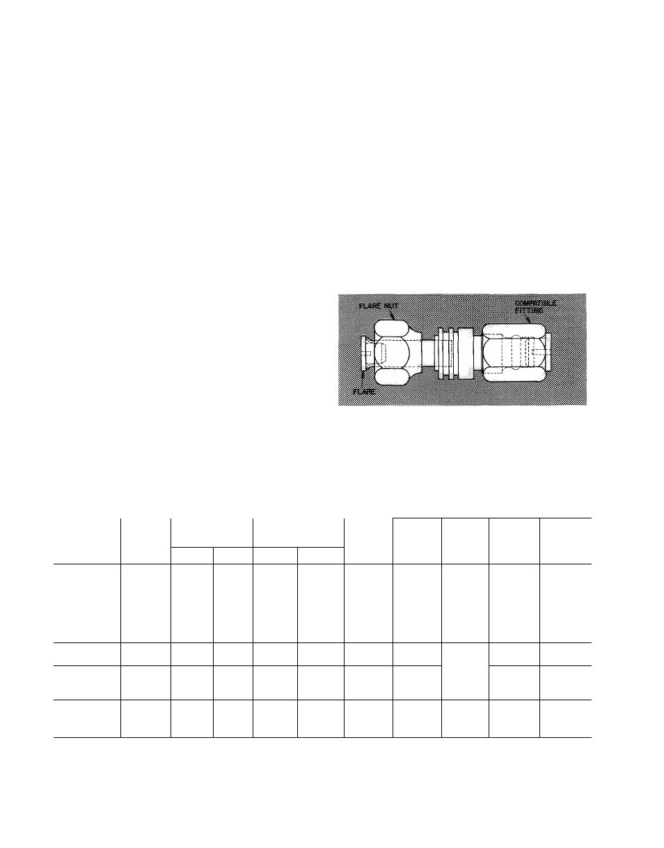
Step 6 — Connect Refrigerant Lines
to fittings on
unit suction and liquid service valves (Fig. 1).
Liquid service valve has flare fitting; suction service
valve has Compatible Fitting. Make suction line
connection first. Slide flare nut on liquid line, then
flare and connect liquid line. (Do not disassemble
AccuRater.) Unit Compatible Fitting permits
mechanical (quick-connect) or sweat connection as
described below. It is not necessary to flare system
liquid line if an accessory flare to Compatible
Fitting coupler is used for liquid line connection.
See Accessory Coupler (Fig. 5).
38CQ044,048 UNITS - When using 1-1/8 in.
field-supplied suction line, remove suction line
adapter taped to compressor suction line. Sweat
connect refrigerant suction line to 1-1/8 in. end of
adapter. Connect 3/4-in. end of adapter to unit
suction line Compatible Fitting.
When a 7/8-in. field-supplied suction line is
used on 38CQ039, a field-supplied 3/4-in. to
7/8-in. suction line adapter must be provided (not
required if 38CQ accessory tubing is used).
MECHANICAL CONNECTION TO COMPATIBLE
FITTING (Mate one set of connections at a time.)
1. Loosen nut on Compatible Fitting one turn. Do
not remove.
2. Remove plug and be sure 0-ring is in the groove
inside the Compatible Fitting.
3. Cut tubing to correct length.
4.
Insert tube into Compatible Fitting until it
bottoms.
5. Tighten nut until it bottoms on back coupler
flange. Keep tube bottomed in Compatible
Fitting while tightening nut.
SWEAT
CONNECTION
TO
FITTING (Use refrigerant tubing.)
COMPATIBLE
1
.
rubber 0-ring and
2
.
3.
4.
5.
Remove locking nut,
Schrader core from valve.
Cut tubing to correct length.
Insert tube in Compatible Fitting. Wrap top and
bottom of service valves in wet cloth to prevent
damage by heat. Solder with low temperature
(450 F) silver alloy solder.
Replace Schrader core.
Evacuate or purge system with field-supplied
refrigerant.
ACCESSORY FLARE TO COMPATIBLE COU
PLER is shown in Fig. 5. Attach flare nut on
coupler to flare fitting on unit liquid service valve.
Connect liquid line to Compatible Fitting using
mechanical or sweat connection. When mechanical
connection is made, use 2 wrenches when tighten
ing Compatible Fitting nut — one to hold coupler
and one to tighten nut. Liquid line must be flared
if coupler is not used.
Fig. 5 — Accessory Coupler
ELECTRICAL DATA AND WIRING
Field wiring must comply with local and
national fire, safety and electrical codes. Voltage to
unit must be within ± 10% of voltage indicated on
Table 4 — Electrical Data (60-Hz)
UNIT
V/PH
OPER
VOLTAGE*
COMPR
FAN
FLA
Power
Wire
Size
(AWG)
Max
Ft
Wire
Gnd
Wire
Sizef
(AWG)
Max
Fuse
Ampsi
Max
Min
LRA
RLA
38CQ015
41
9.0
.9
14
31
14
20
38CQ020
65
10.3
.9
12
40
12
20
38CQ027
82
17.7
2.4
10
42
10
40
38CQ033
230/1
254
207
88
19.8
2.4
10
36
10
45
38CQ039
94
22.2
2.4
10
33
10
50
38CQ044
106
25.0
2.4
8
46
8
50
38CQ048
106
25.0
3.0
8
46
8
50
200/
13.0/
2.0/
30/
38CQ033
230/3
254
180
87
11.5
2.0
12
40
12
25
38CQ039
79
17.4
2.4
12
31
12
40
38CQ044
200/3
229
180
87
18.6
2.4
10
35
10
40
38CQ048
87
18.6
3.0
10
35
10
40
38CQ039
67
15.0
2.4
12
41
12
35
38CQ044
230/3
254
207
70
16.7
2.4
12
36
12
35
38CQ048
70
16.7
3.0
12
36
12
35
BRANCH CIRCUIT
FLA
— Full Load Amps
LRA
— Locked Rotor Amps
RLA
— Rated Load Amps
*Permissible limits of the voltage range at which the units will
operate satisfactorily
fRequired when using nonmetallic conduit
^Maximum dual element fuse size
NOTES:
1
Fan motors are 200-v or 230-v, single phase
2
All units have 24-v control circuit which requires external
power source
3
Copper wire sizes based on 60 C Use copper or copper-clad
aluminum
wire
only
Use
latest
National
Electrical
Code
for
wire sizing
V