Fig. 31 — component location – Carrier 38CQ User Manual
Page 14
Attention! The text in this document has been recognized automatically. To view the original document, you can use the "Original mode".
Compressor Removal
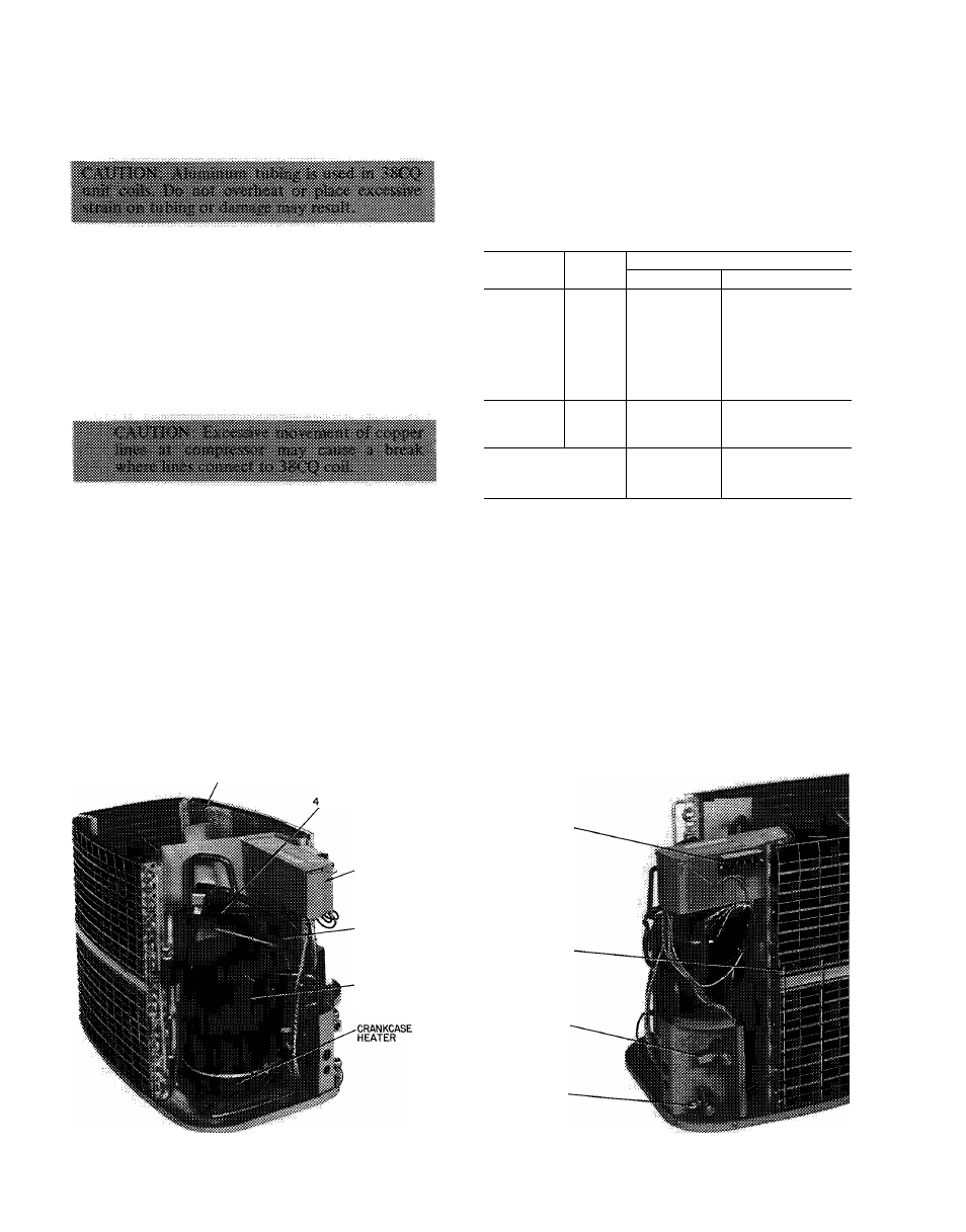
— See Table 7 for compressor
information and Fig. 31 for component location.
Follow safety codes, and wear safety glasses and
work gloves. Have quenching cloth available
(Step 7).
1. Shut off power to unit. Remove unit top
access cover and rear access wrapper.
2. Remove refrigerant from unit using refrigerant
removal methods described in Carrier Standard
Service Techniques Manual, Chapter 1.
3. Disconnect compressor wiring at compressor
terminal box.
4. Using a tubing cutter, cut suction and dis
charge lines at convenient place near com
pressor for easy reassembly to new compressor
with copper slip couplings.
5. Remove crankcase heater from compressor
base.
6. Remove compressor hold-down bolts and lift
compressor out.
7. Carefully unbraze suction and discharge line
piping stubs from compressor. If oil vapor in
piping stubs ignites, use quenching cloth.
8. Braze piping stubs (removed in step 7) on new
compressor.
9. Clean system. Add new liquid line heat pump
filter-drier as described below.
10.
Install new compressor in unit. Braze suction
and discharge lines to compressor piping stubs
(at points where cut, step 4) using field-
supplied copper couplings. Make sure com
pressor hold-down bolts are in place. Connect
wiring.
11. Evacuate and recharge unit.
FILTER-DRIER — Install accessory heat pump
filter-drier (Table 3) in system liquid line when
refrigerant system is opened for service as de
scribed under Compressor Removal. Position drier
in liquid line at convenient location. Do not use a
standard single-pass filter-drier.
Table 7 — Compressor Data
UNIT
V/PH
PRODUCTION —
Model*
Oil Recharge (oz)
38CQ015
38CQ400994
20
38CQ020
MD2023HB
44
38CQ027
MD3023HB
44
38CQ033
230/1
MC3423HB
44
38CQ039
PC4Ó16HD
64
38CQ044
PC5316HD
64
38CQ048
PC5316HD
64
38CQ039
PF4616HD
64
38CQ044
200/3
PF5316HD
64
38CQ048
.
PF5316HD
64
38CQ039
PG4616HD
64
38CQ044
230/3
PG5316HD
64
38CQ048
PG5316HD
64
‘Refer to Service Parts catalog for replacement compressor
model numbers
Pumpdown Procedure (Cooling Cycle)
— The
38CQ units may be pumped down in order to
make repairs on low side of system without losing
complete refrigerant charge. Ensure unit is in
cooling mode.
1. Attach pressure gage to suction service valve
service port.
2. Frontseat the liquid line valve.
3. Start unit and run until suction pressure reaches
5 psig (see Caution).
4. Shut unit off and frontseat suction valve.
5. Vent remaining pressure to atmosphere.
FAN COMPARTMENT
-WAY VALVE
CONTROL BOX
DISCHARGE LINE
MUFFLER
(039,044,048)
COMPRESSOR
CONTROL WIRING
TERMINAL BOARD
ACCUMULATOR'
SUCTION
LINE
SERVICE VALVE-
LIQUID LINE
SERVICE VALVE
Fig. 31 — Component Location
14