Carrier 38CQ User Manual
Carrier Conditioners
Attention! The text in this document has been recognized automatically. To view the original document, you can use the "Original mode".
Carrier Parkway • Syracuse, N Y 13221
Heat Pump - Outdoor Section
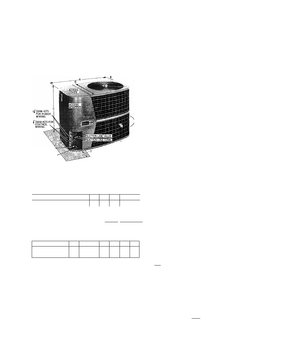
4'0" OVERHEAD SPACE REQ'D
FOR SERVICE AND AIRFLOW
LIQUID LINE CONN
LIQUID LINE VALVE
0 AIRFLOW
CLEARANCE
(BOTH SIDES)
i'-0"(B0TH SIDES)
ra SPACE REQ'D FOR SERVICE
^ AIRFLOW
Certified dimension drawings are available on request
Fig. 1 — Dimensions and Connections (Table 1)
Table 1 — Installation Data (Fig. 1)
UNIT DIM. (ft-in.)
Length
A
Width
B
Height
C
UNIT 38CQ
; 015 1 Ò20
027
033
039
044
048
OPER WT (lb)
TÌ45 j_160
166
180
210
212
220
REFRIG CONN (in.)
Suction* (ODF)
Liquid* (ODF)
2-10V4
1-10
I -4^1
-
4
%
11 -4Vs[ 2-0)41 2-0yB|2-0VB 12-6Vs
Compatible Fitting (Suet) & Flare (Liq)
Ys I % I
%
%
‘Recommended field supplied refrigerant line sizes
UNIT 38CQ
015
020 [027
033
039
044t 048t
SUCTION (in. ODF)
LIQUID (in. ODF)
5/
78
Vs
1
^4
%
%
V
78
f
Z 1
IV
b
tMay use 7/8-in accy tubing package (slight capacity loss) See p 3
NOTES:
1 Maximum length of interconnecting tubing is 50 feet
2
Units 38CQ044, 048 factory supplied with 3/4 to 1-1/8 in suc
tion
valve
adapter
(field
installed)
for
field-supplied
1-1/8
in
suction line
INSTALLER'S
PRELIMINARY
SURVEY
Step 1 — Unpackage Unit
— Move heat pump to
final location. Open carton at end marked
“compressor end.” Slide unit from carton taking
special care to not damage service valves or grilles.
Step 2
—
Inspect Equipment
— File claim with
shipping company if shipment is damaged or
incomplete.
Step 3 — Complete or Consider the Following
before installing the 38CQ unit.
Consult local building codes and National
Electrical Code (NEC) for special installation
requirements.
When installing unit, allow sufficient space for
airflow clearance, wiring, refrigerant piping and
servicing unit. Position unit so water or ice from
roof will not drop directly on top of unit.
Make provisions for condensate drainage and
defrost water disposal whether unit is installed on
ground or roof. (Make sure unit base pan drainage
holes are not blocked.) See Mounting Pad for
details.
Roof
installation
method
for
38CQ
depends on building construction and special re
quirements of local codes. Roof must be capable of
supporting unit weight. Maximum allowable ver
tical distance between indoor and outdoor sections
is 50 feet. See Table 2.
Use an indoor coil with a bleed-type expansion
device. (See Table 2 for Carrier approved indoor
sections.) If coil does not have a bleed-type
expansion device, it may be necessary to add an
accessory start capacitor and relay to heat pump.
This would require removing compressor start
thermistor (PTC device) on units so equipped. It is
recommended that 38CQ units be used with
Carrier approved indoor sections, all of which are
equipped with a bypass type AccuRater'^^ (bleed-
type expansion device).
Table 2 — Carrier Approved 38CQ System Data
OUT
DOOR
UNIT
^ .38CQQ15
38CQ020
38CQ027
38CQ033
38CQ039
38CQ044
38CQ048
REFRIG
ERANT
INDOOR UNIT
Fan
Coi
22
4gAQpi8
^^^40AQ024
40AQ024*
40AQ030
40AQ030*
40AQ036^_
40FSJI60|28MQ036
40AQ036*
40FS160
4ÒFSÌ60
40FS160
40FS200
40FS200
28MQ036'
'28MQ042
28MQ042*
28MQg48^
28MQ048''
Accu-
Rafer
Piston
.
II
2
4*
4
.
6
*
..
6
. 6
.. .Tt...
.
If
.
7
8
*
j
HEIGHT (ft)
I
Indoor Unit
; Above
1 Be low
Outdoor Unit
50
50
‘Indoor
units
that
require
replacement
of
AccuRater
refrigerant
control
piston
for
optimum
performance
when
used
with
specified
outdoor unit The 38CQ048 is factory supplied with no 8 piston for
indoor unit (28MQ048)
(g) Carrier Corporation 1977
38CQ400105 B
Form 38CQ-6SI