Carrier 38CQ User Manual
Page 7
Attention! The text in this document has been recognized automatically. To view the original document, you can use the "Original mode".
(
OD (liquid line), respectively, using refrigerant
weights shown in table below. (Twenty-five feet of
3/8-in. OD tubing contains 14.4 oz of R-22.) Add
R-22 charge to system if liquid line is over 25 ft;
remove charge if liquid line is shorter than 25 feet.
LIQUID LINE 1 OUNCES OF ^22/FT LENGTH
DIAM (in.)
OF LIQUID LINE
3/8
5/16
1/4
58
36
21
Table 6 — Service Data
UNIT 38CQ
1 015,
1 020
027
033
039
044
048
R-22 CHG
]
(Ib-oz)
1
4-10
4-1 1
6-5
7-11
7-13
7-10
REFRIG CONTROL
A
ccuRater*^^
(Bypass Type
)
FAN
1
Prope Her -
Direct
Drive
Cfm
2600
2600
2800
2800
1
2600
3400
Rpm
1
1075
Diam (in.)
1 17
17
18
18
16
18
Motor Hp
1/8
1/4
1/4
1/4
1/4
1 / 2
When recharging is necessary during heating or
cooling season, weigh in total charge indicated in
Table 6. (Charge must be weighed in during heating
season.) Remove any refrigerant remaining in
system before recharging. If system has lost com
plete charge, evacuate system to 500 microns (29.7
in. vacuum) before recharging. Service port connec
tions are provided on liquid and suction line service
valves for evacuation and charging. (See Fig. 32 for
correct service port location on cooling and heating
cycles.) DiaTa-charge charging cylinder is an
accurate device used to recharge systems by
weight. These cylinders are available at refrig
eration supply firms.
To check and/or adjust charge during cooling
season, use correct Cooling Cycle Charging Chart
(Fig. 9, 11, 13, 15, 17, 19, 2 1 , 2 3 , 2 5 , 2 7 , 29) and
follow Charging Chart Method below. The charging
chart may also be used as an alternate method of
recharging system.
To check system operation during heating
cycle, use correct Heating Cycle Operation Check
Chart (Fig. 10, 12, 14, 16, 18, 20, 22, 24, 2 6 , 2 8 ,
30). These charts indicate whether a correct
relationship exists between system operating pres
sures and air temperatures entering indoor and
outdoor units. If pressure and temperature lines do
not intersect on chart, the system refrigerant
charge may not be correct or other system abnor
malities may exist. Do not use Operation Check
Charts to adjust refrigerant charge. Weigh charge
into system.
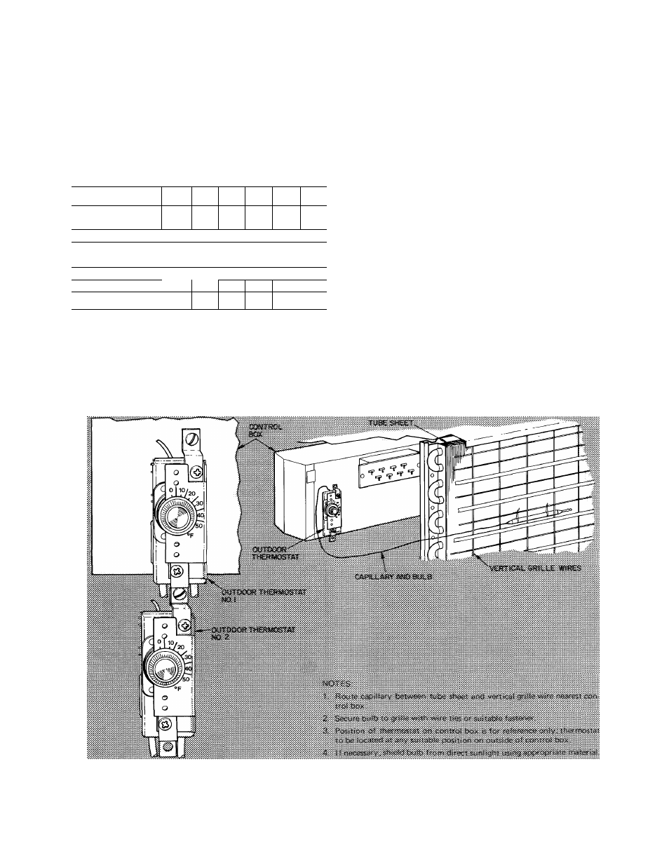
a. 2 — Thermostat Assembly
b. Capillary Tube Routing
^ Fig. 8 — Outdoor Thermostat Installation Details
7