Table 3 — accessories, Piping connections, Before connecting refrigerant lines – Carrier 38CQ User Manual
Page 3
Attention! The text in this document has been recognized automatically. To view the original document, you can use the "Original mode".
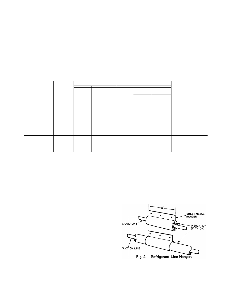
Table 3 — Accessories
PART NO.
DESCRIPTION
38CQ900081
38C 0900111
Low-Voltage Control — Honeywell Thermostat HH07AT071 and
Thermostat Subbase HH93AZ073 — (Automatic Changeover)
38CQ900182
38GS900381
Low-Voltage Control — Honeywell Thermostat HH07AT071 and
Thermostat Subbase HH93AZ075 — (Manual Changeover)
Service Sentry (Six HN65CT002)
____
38CQ900061
38CQ900091
Start Capacitor and Relay Package
Flare
(3/8-in.)
to
Compatible
(3/8-in.)
Couplings
(Two-Pack)
Liquid Line Filter-Drier
38RQ900001
Emergency Heat Relay (Required with 2 outdoor thermostats.)
(Service Parts)
38RQ900021
1
h
H22AG110
Outdoor
Thermostat
(Six
38RQ900032)
Optimizer Control
38CQ900141
Solid State Time Guard (24 volt)
TUBING
Length
Liquid
Suction*
TUBING
UNIT
1 ube bnd
PACKAGE
(ft)
OD
1 ube End
OD
OD (in.)
(in.)
OD (in.)
(in.)
Evap
Cond
38GC900031
10
%
%
Va
V4t
Va
38GC900041
18
%
Va
Va
V4t
Va
38GS900221
25
%
Va
Va
V4t
Va
38CQ015,020
38GC900061
35
Ha
Va
Va
V4Î
Va
38GC900191
50
V
4
___
Va
Va
V4t
V4
38GC900071
10
V
Va
4
V
4
y
4
38GC900081
18
V
4
V
4
V
4
y
4
38GC900091
25
4
V
4
V
4
V
4
y
4
38CQ027,033
38GC900101
35
V4
Va
V4
V
4
y
4
38GC900m
50
V
4
Va
V
4
V
4
y
4
38CQ900001
18
V
4
V
4
Vat
V
4
y
4
38CQ9000n
25
4
Va
Vai
4
4
38CQ039,044,048
38CQ900021
35
V
4
Va
V
4
V
4
V
4
38CQ900031
50
V4
Va
Vai
4
*Suction line is insulated and has a 90 bend at one end
fFor 5/8-in evaporator connection, cut off 3/4-in end
ICapacity reduction may occur when 7/8-in accessory tubing is used
on 38CQ044.048
PIPING CONNECTIONS
The 38CQ units can be connected to indoor
units using Carrier accessory tubing package or
field-supplied tubing of refrigerant grade. See
Table 1 (with notes) for unit piping connection
type, size and line size recommendations and
Table 3 for accessory tubing sizes. Maximum
length of refrigerant piping allowed is 50 feet
A capacity reduction will result if accessory
tubing is used in 38CQ044,048 systems. For
example, when a 25-ft, 7/8-in. accessory tubing
package is used, there will be a capacity reduction
of 1-1/2%. For maximum capacity, use 1-1/8 in.
suction line as recommended in Table 1.
When other than 25 ft of interconnecting
piping is used, follow special requirements de
scribed in Refrigerant Charging. Do not use less
than 10 ft of accessory liquid line. Do not cut
5/16-in. or 1/4-in. liquid line. Do not cut 7/8-in.
suction line. Bend or coil to fit.
Do not use damaged or contaminated tubing.
Always evacuate or purge evaporator coil and
tubing system (use field-supplied refrigerant, not
unit refrigerant).
When making tubing connections, be sure to
provide clearance at unit for electrical connections.
To assure noise-free installation, isolate refrig
erant lines from ductwork and framing or where
they run thru stud spaces, enclosed ceilings or pipe
chases. Use isolation hangers (Fig. 4), as rigid
fastening may transmit pulsations to structure,
creating an objectionable rumble. Do not attach
liquid line to uninsulated suction line. When
running thru structure, surround all lines with 1-in.
insulation to prevent transmission of vibration.
Before Connecting Refrigerant Lines,
replace the
AccuRater'^'''^ refrigerant control piston in the
indoor coil as required. See Table 2. The 38CQ048 is