Step 8 — bring line power leads into unit, Fig. 6 — control circuit connections, Step 7 — install a branch circuit fused disconnect – Carrier 38CQ User Manual
Page 5: Step 10 — see indoor unit and electric heater, Step 11 — control power wiring (24 v)
Attention! The text in this document has been recognized automatically. To view the original document, you can use the "Original mode".
f
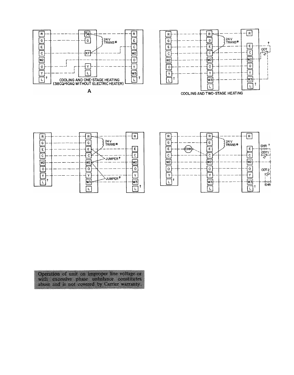
THERMOSTAT
SUBBASE
HH93AZ073 OR
HH93AZ075
40AQ FAN COIL
COOLING CONTROL KIT
TERMINAL BOARD
38CQ
TERMINAL
BOARD
THERMOSTAT
SUBBASE
HH93AZ0730R
HH93AZ075
40AQ OR 40FQ
ELECTRIC HEATER
TERMINAL BOARD
38CQ
TERMINAL
BOARD
(38CX) WITH 40AQ OR 40FS/28MQ
EQUIPPED WITH ELECTRIC HEATER;
EMERGENCY HEAT, ONE OUTDOOR THERMOSTAT)
THERMOSTAT
SUBBASE
HH93AZ073 OR
HH93AZ075
40AQ OR 40FQ
ELECTRIC HEATER
TERMINAL BOARD
38CQ
TERMINAL
BOARD
COOLING AND TWO-STAGE HEATING
(38CQ WITH 40AQ OR 40FS/28MQ
EQUIPPED WITH ELECTRIC HEATER;
EMERGENCY HEAT, NO OUTDOOR THERMOSTATS)
B
EHR
— Emergency Heat Relay
ODT
— Outdoor Thermostat
_______ Factory Wiring
_______ Field Wiring
THERMOSTAT
SUBBASE
HH93AZ073 OR
HH93AZ075
40AQ OR 40FQ
ELECTRIC HEATER
TERMINAL BOARD
38CQ
TERMINAL
BOARD
COOLING AND TWO-STAGE HEATING
(38CQ WITH 40FS/28MQ
EQUIPPED WITH ELECTRIC HEATER;
EMERGENCY HEAT, TWO OUTDOOR THERMOSTATS)
*Transformer (60 va) located in cooling control kit or electric heater
fTerminal L is identified as terminal X on some former thermostats
(Required for accessory Service Sentry)
:|;Remove
factory-installed
jumpers
(connection
B)
when
installing
outdoor thermostats (ODT)
Fig. 6 — Control Circuit Connections
nameplate. On 3'-phase units, phases must be
balanced within 2%. Contact local power company
for correction of improper line voltage.
When making electrical connections, provide
clearance at unit for refrigerant piping connections.
See Table 4 for recommended wire and fuse sizes.
Step 7 — Install a Branch Circuit Fused Disconnect
of adequate size to handle unit starting current.
Provide a separate fused disconnect for outdoor
unit, indoor unit and for each accessory electric
heater circuit as required. (See Indoor Unit and
Electric Heater Installation, Start-Up and Service
Instructions.) Locate disconnect(s) within sight of
and readily accessible from the unit, per section
440-14 of National Electrical Code (NEC).
Step 8 — Bring Line Power Leads Into Unit —
Extend leads from fused disconnect thru hole
provided in service embossment (Fig. 1) and thru
7/8-in. hole into control box.
Step 9 — Connect Ground Lead to a Ground Lug
in Control Box
for safety. Connect power wiring.
See Fig. 7. Splice line power leads to yellow and
black pigtails on single-phase units or to black
pigtails (3) on 3-phase unit. Use wire nuts supplied
with unit. Tape each connection.
Step 10 — See Indoor Unit and Electric Heater
Installation, Start-Up and Service Instructions for
line power wiring details. All control wiring is
shown in this booklet.
Step 11 — Control Power Wiring (24 v)
is brought
thru hole in unit service embossment. Fig. 1.
Connect leads to control wiring terminal board
(located on outside of control box) as shown in
Fig. 6.