Mouimtirjttp – Carrier 38CQ User Manual
Page 2
Attention! The text in this document has been recognized automatically. To view the original document, you can use the "Original mode".
MOUIMTirJtTP^
Step 4 — On the Ground: Mount Unit on a Solid,
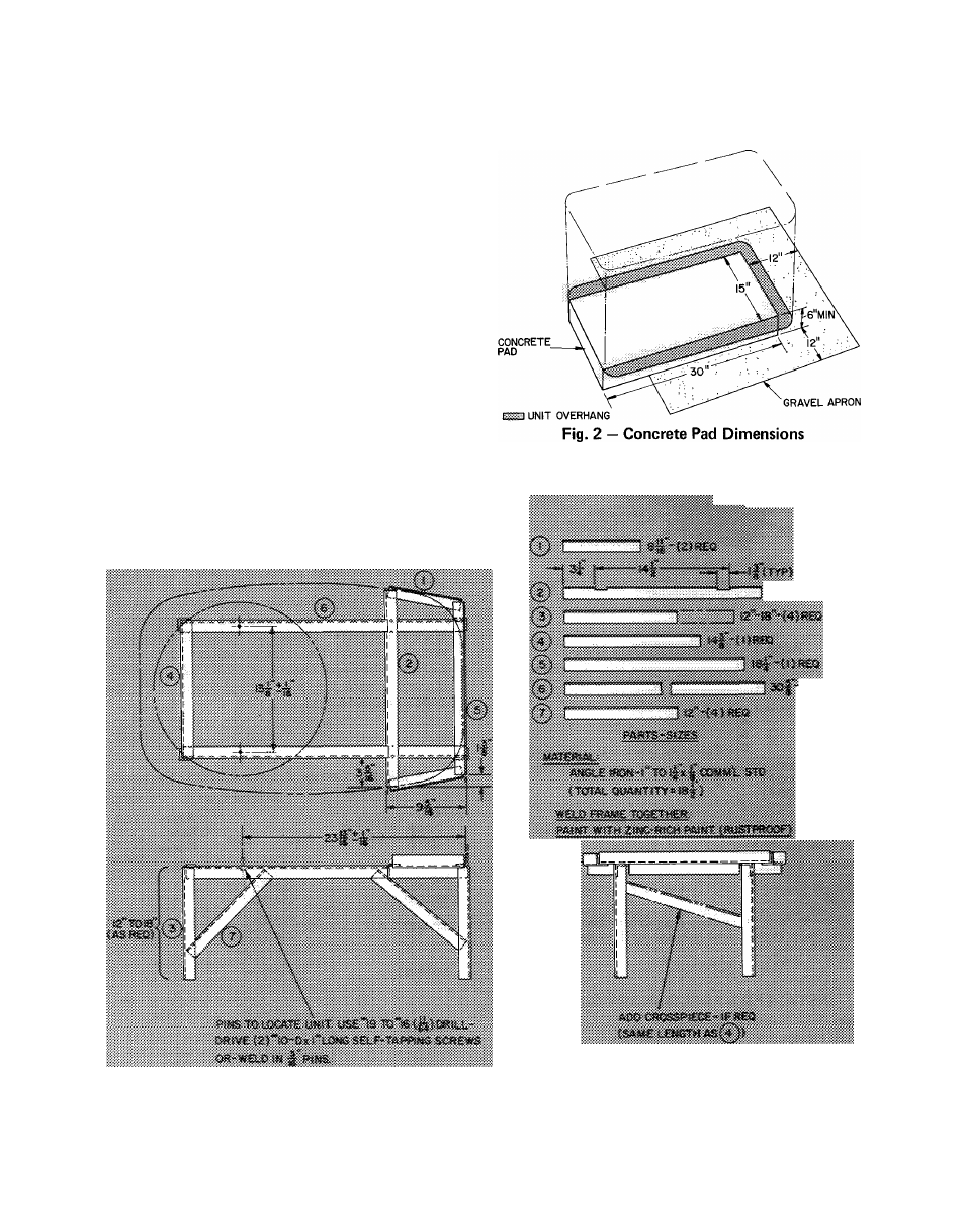
Level Concrete Pad.
See Fig. 2 for pad dimensions.
Position unit so that coil drainage holes in base pan
overhang the pad. Make sure pad does not obstruct
drainage holes (holes drain water during heating
and defrost cycles). Unit can be attached to pad
with mastic adhesive or by drilling holes in base
pan for 1/4-in. mounting bolts.
Construct pad a minimum of 6-in. thick to
provide clearance under holes for drainage and ice
buildup. In areas where prolonged subfreezing
temperature or heavy snows occur; increase clear
ance to 12 to 18 in. by constructing an angle iron
frame to support unit 12 to 18 in. off concrete
base. Cross angle of frame must not obstruct coil
drainage holes. See Fig. 3 for recommended frame
construction. Extend a 12-in. gravel apron around
pad for condensate and defrost water drainage
field.
Step 5 — On the Roof: Mount Unit on a Level
Platform or Frame:
Unit must be elevated for
proper clearance as described under ground in
stallation above. Roof design and water drainage
must be planned to prevent unit from setting in
water. Flash all roof openings to prevent leaks.
«AtMtAK'tMV.VA'Kry.-
mtm
Fig. 3 — Heat Pump Mounting Frame