Figure 1, Attention – Tuffy Security 149 User Manual
Page 2
Page 2 of 2 – 12/20/06 – Rev10/12/2012
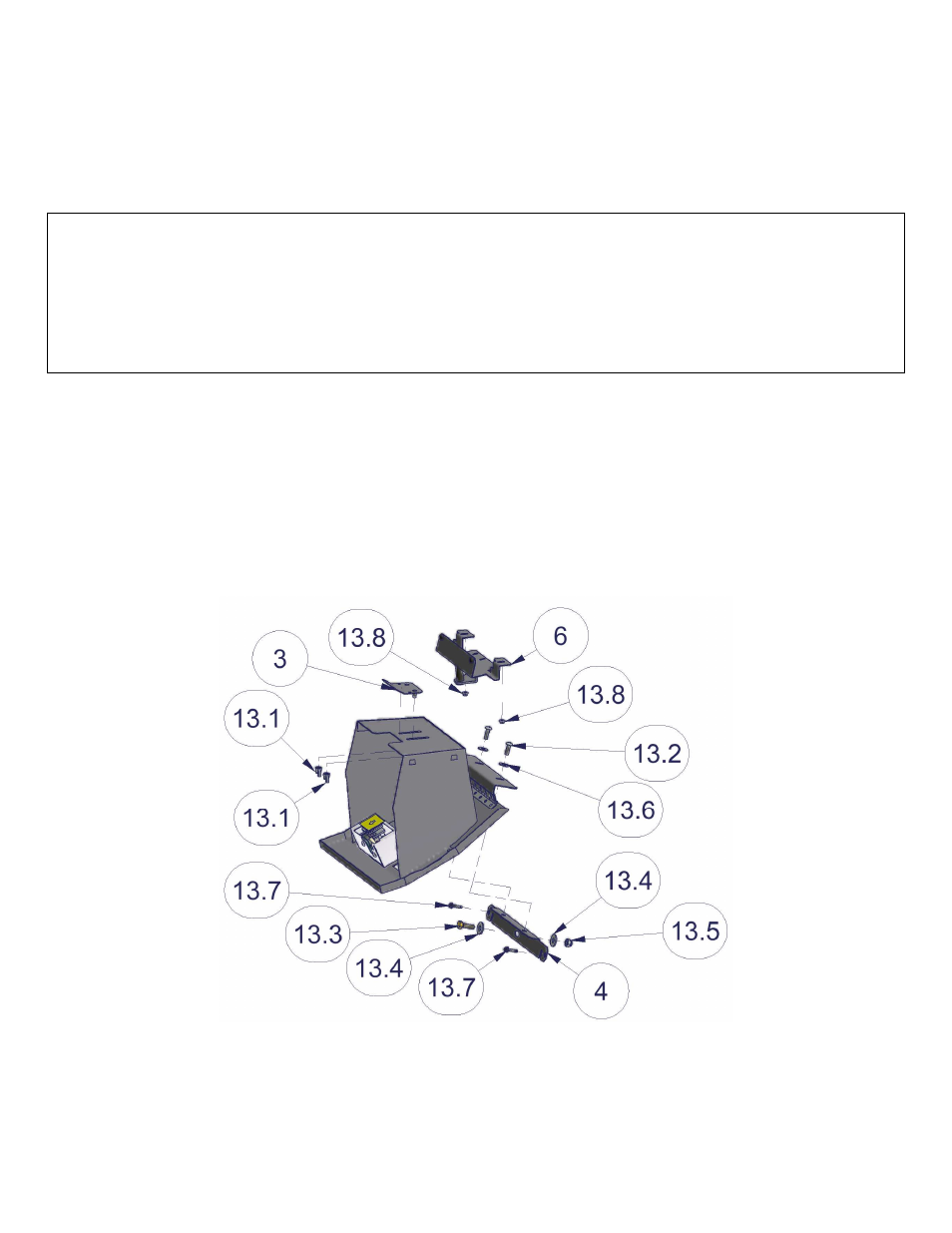
4. Remove the original two nuts #13.8 at the top inside the glove box opening by where the lock catch was removed.
Save these you will reuse them. (See Figure 1)
5. Maneuver #4 Mounting bracket between the plastic dash panel and the frame at the bottom of the glove box opening
then re-fasten the (2) original screws #13.7. (See Figure 1) If the other original dash screws were removed they can
be re-fastened and the plastic panel can be popped back in.
6. Mount the #6 Latch Bracket to the inside top of the dash opening by re-fastening the original nuts #13.8. (See Figure
1)
OPTIONAL SECURITY STEP
WARNING! - Make sure that there is nothing behind the dash that will be damaged by the drill bit when drilling.
(2007-2010 JK) Drill a 3/8” hole in the dash frame corresponding with the center hole in Mounting Bracket #4. Fasten
using 5/16 x 1” bolt #13.3, 5/16 Nut #13.5, and 5/16” Washers #13.4. (See Figure 1)
(2011-up JK) Drill a 5/8” hole in the plastic dash panel and subsequently drill a 3/8” hole in the dash frame corresponding
with the center hole in Mounting Bracket #4. Fasten using 5/16 x 1” bolt #13.3, 5/16 Nut #13.5, and 5/16” Washers #13.4.
(See Figure 1)
7. Position the Glove box in the dash so the mounting holes by the hinge line up with the holes in the #4 Mounting
Bracket and fasten them together using (2) ¼-20 x ¾ screws #13.2 and (2) ¼ Washers #13.6. (See Figure 1)
8. Check the lock operation and fit clearances. All the mounting holes are obrounded so the fit can be adjusted by
loosening the fasteners and maneuvering the box as required.
9. Fasten the #3 Door stop to the back of the Glove box using (2) ¼-20 Wingnuts #13.1. Enable it by partially shutting
the Glove box past the #6 Latch bracket, slide the #3 Door stop up and tightening the Wingnuts. When the door is
opened the #3 Door stop will hit the #6 Latch bracket preventing the door from opening further. (See Figure 1)
FIGURE 1
ATTENTION:
FREQUENT LUBRICATION IS NECESSARY ON THE LOCKING SYSTEM
The pushbutton lock contains an “O” ring seal to protect the interior from dust and water. If this mechanism is not lubricated regularly it will become
difficult to operate and it may not return to its home position preventing the key from operating the lock. If this happens simply pull up on the pushbutton
to manually bring it back to its home position. Lubricate the pushbutton with a light lubricant such as silicone spray. The pushbutton may have to be
periodically disassembled and cleaned.
Call (970) 564-1762 for Technical Support