Figure 1 – Tuffy Security 219 User Manual
Page 2
Tuffy Security Products,
www.tuffyproducts.com
, (970) 564-1762 Page 2 of 2 - 12/01/2009
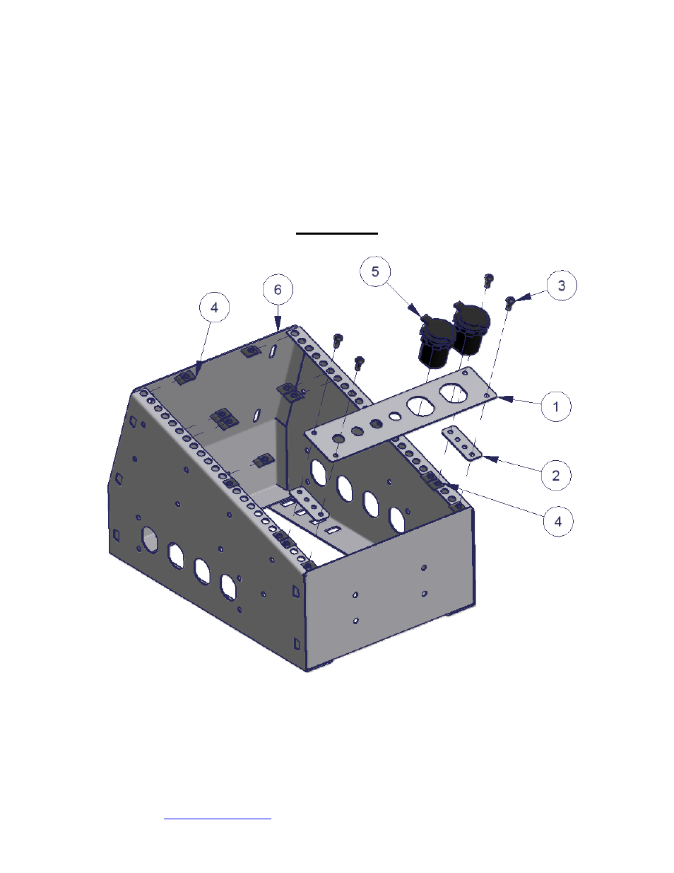
3. Install the snap fit U-Nuts (#4) in the appropriate locations so that they line up at each corner of the faceplate as shown in
Figure 1.
4. If applicable, install the Power Ports (#5) and/or any additional switches or accessories into the faceplate (#1).
NOTE: It is the responsibility of the installer to wire any electrical accessories properly to ensure that there is no
damage to the vehicle’s electrical system or to any attached components. Consult an automotive wiring specialist if
necessary.
5. Install the accessory faceplate (#1) and spacer plate (#2) onto the Tuffy console using the four cap screws (#3) as shown in
Fig. 1. Hand tighten the cap screws until firmly tight but be careful not to over tighten.
FIGURE 1
Call (970) 564-1762 for Technical Support
- 082 (2 pages)
- 089 Manual (3 pages)
- 089 Installation Manual (1 page)
- 101 (2 pages)
- 073 (3 pages)
- 198 (2 pages)
- 189 (1 page)
- 292 (2 pages)
- 282-BTL (1 page)
- 137 (2 pages)
- 295 (3 pages)
- 862 (2 pages)
- 863 (3 pages)
- 311 (2 pages)
- 312 (2 pages)
- 046 (3 pages)
- 145 (4 pages)
- 131 (2 pages)
- 297 (3 pages)
- 296 (3 pages)
- 240 (10 pages)
- 238 (2 pages)
- 058 (3 pages)
- 195 (2 pages)
- 144 (2 pages)
- 274 (10 pages)
- 139 (3 pages)
- 157 (10 pages)
- 052 (2 pages)
- 164 (1 page)
- 104 (1 page)
- 043 (1 page)
- 027 (2 pages)
- 035 (2 pages)
- 108 (2 pages)
- 149 (2 pages)
- 049 (2 pages)
- 036 (2 pages)
- 160 (3 pages)
- 289 (2 pages)
- 287 (3 pages)
- 283 (3 pages)
- 309 (2 pages)
- 182 (2 pages)