Console step 4 - connecting component cables, E sprayer control – TeeJet 844-E Sprayer Control User Manual
Page 13
9
98-70006-ENUS R4
844-E Sprayer Control
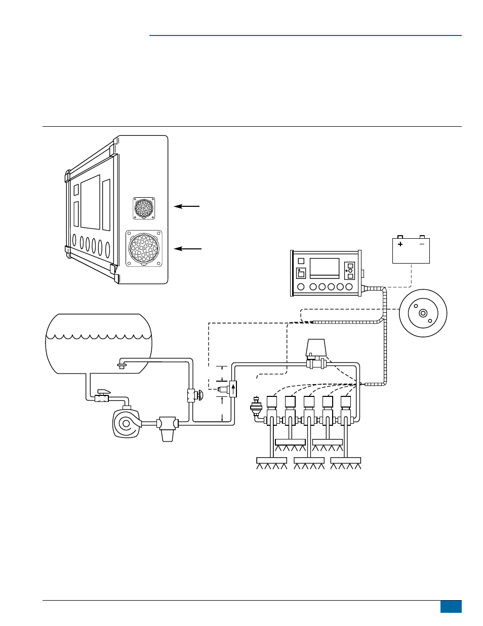
Console Step 4 - Connecting Component Cables
Now that you have the console installed you can begin connecting it to the other components of the 844 system. The standard kit contains a main
cable that attaches to the boom control valves, the pressure regulating valve, flow meter and/or pressure sensor, a magnetic wheel speed sensor,
and a proximity speed sensor or radar speed sensor. Lay out each of the valve and sensor leads before installing the sprayer components to be
sure the cables are long enough in length from the sensor connections to the 844 console connection. If your installation requires longer cables,
several extension cables are available. If an exit hole has to be cut in the cab, be sure the edges are deburred and protected to prevent damage to
the cables.
Figure 13: Wiring Diagram
844 SPRAYER CONTROL
TANK
POWER
JET AGITATOR
SPEED SENSOR
SOLENOID VALVES
BOOM SECTIONS
STRAINER
TANK SHUT-OFF
CENTRIFUGAL
PUMP
AGITATOR
VALVE
PRESSURE
TRANSDUCER
(IF USED)
PRESSURE
REGULATING
VALVE
10-12˝
(25-35 CM)
5-7˝
(12-17 CM)
FLOW METER
(IF USED)
COMMUNICATION
CABLE CONNECTION
MAIN CABLE
CONNECTION