Speed step 2 - installing the wheel magnets, Speed step 3 - installing the magnetic sensor, E sprayer control – TeeJet 844-E Sprayer Control User Manual
Page 10
6
www.teejet.com
844-E Sprayer Control
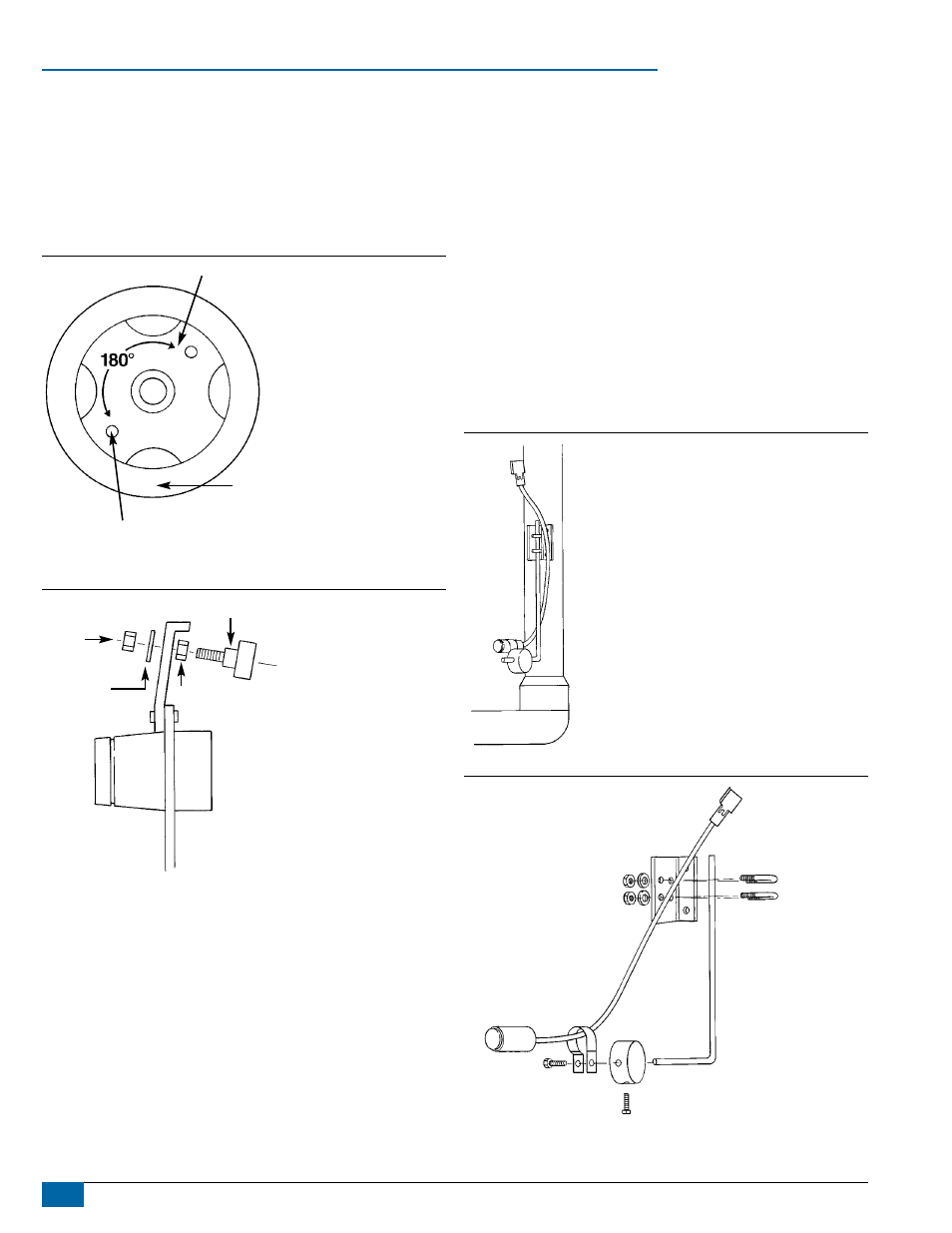
Speed Step 2 - installing the wheel Magnets
Check for pre-drilled holes in the wheel rim. If pre-drilled holes are not
available, layout a pattern as shown in Figure 7 and drill two 3/8″ (10
mm) holes near the outer edge of the rim if possible, and 180° from
each other.
Place the magnets into each of the two holes on the inside rim and
securely fasten them using the nuts and washers provided.
Figure 7: Magnet Locations
TIRE
WHEEL
3/8˝ (10 mm)
HOLE FOR
MAGNET
Figure 8: Magnet Assembly
NUT
NUT
MAGNET
WASHER
Speed Step 3 - installing the Magnetic
Sensor
The flat, pressed L bracket of the wheel speed sensor kit should be
secured to a vertical member near the non-driven wheel. The round,
right angle steel bracket is then secured to the flat bracket with the
two U-bolts and necessary hardware provided. The round, right angle
bracket is then used to secure the magnetic sensor mounting clamp.
The magnetic sensor should be inserted into the mounting clamp and
positioned within 1/8″ to 3/8″ (3-10 mm) of the wheel magnet. Tighten
the sensor clamp using the clamp screw per Figure 10.
Your installation will likely vary from the example. It may be necessary
to customize the installation to accommodate your specific machine.
Keep in mind that the two magnets must be spaced an equal distance
around the wheel. The magnetic sensor must be mounted in-line with
the magnets and positioned within 1/8″ to 3/8″ (3-10 mm) from each
magnet as they pass the Sensor assembly.
Figure 9: Sensor Mounting
Figure 10: Sensor Assembly
CLAMP
SCREW
SENSOR
BRACKET
FLAT
L BRACKET