Magnetic wheel sensor, Radar, Mounting the teejet 844 console – TeeJet 844-E Sprayer Control User Manual
Page 11: Console step 1 - location, Console step 2 - mounting, Magnetic wheel sensor radar, E sprayer control
7
98-70006-ENUS R4
844-E Sprayer Control
Speed Step 4 - Confirming Speed Sensor
installation
Magnetic Wheel Sensor
After your wheel or proximity sensor is installed and once the 844
console is installed and powered up, you can test the speed sensor
installation. Connect the wheel speed or proximity sensor to the sensor
cable, and in turn connect the sensor cable to the 844 console. When
the connection is made, rotate the wheel on which the magnets are
installed. If using a proximity sensor, you will be sensing metal objects
and not magnets. Each time a magnet (metal object for proximity
sensor) passes the sensor a red LED (orange LED for proximity
sensor) on the back of the sensor will light. The LCD display on the
console will also indicate a speed as the sensor receives and sends
electronic pulses.
Radar
If you are using a radar speed sensor it should be connected to the
speed sensor connector on the sensor end cable. An adapter cable
will be necessary when using most radars and are available through
your TeeJet Technologies dealer. The 844 will automatically sense if
the speed sensor is a wheel speed, proximity type or radar type sensor
during calibration. The 844 is automatically adapted to most brands
of radar speed sensors provided that the appropriate adapter cable
is used. If using a radar sensor, the 844 will display rAd during the
calibration procedure.
MoUnting thE tEEJEt 844 ConSolE
Console Step 1 - location
Determine the best location for the control console in the cab or
operator’s compartment. Allow sufficient clearance, approximately 4-5″
(10-12 cm) to accommodate for the cable that will be connected to the
right side of the console.
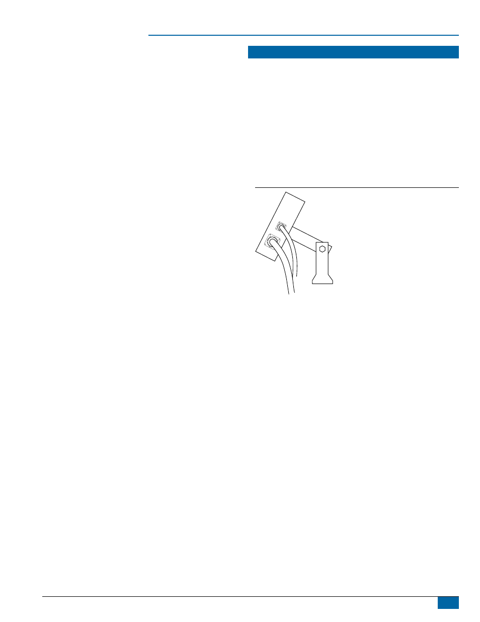
Console Step 2 - Mounting
Mount the console to a firm support within the cab area, and secure
using the slots provided on the top, back, or bottom of the Console.
Although two simple brackets are supplied with the unit, some
additional bracketing may be necessary. The slots in the 844 will accept
1/4″ (6 mm) bolts.
Figure 11: Brackets Provide Angle Adjustment