6 auxiliary power configuration, Installing 4-wire class a smoke detectors -13, 6 auxiliary power configuration -13 – SilentKnight 5895XL 6A Intelligent Remote Power Supply User Manual
Page 33
Hardware Installation
151142
3-13
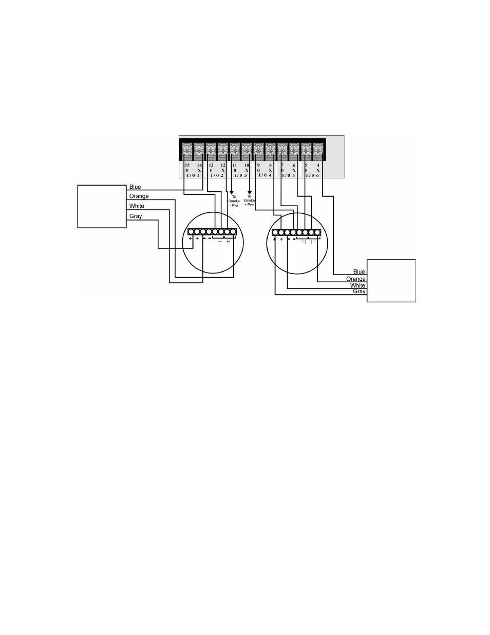
Installing 4-Wire Class A Smoke Detectors
Figure 3-15 illustrates how to install 4-wire Class A detectors.
Conventions used for wiring 4-wire Class A loops:
1. Up to two Class A 4-wire loops can be connected to the control panel at once.
2. Smoke power is supplied to each Class A loop as shown in Figure 3-15.
Figure 3-15 Class A 4-Wire Smoke Detector Connections
Note: In programming any point that uses multiple I/O circuits are always referred to as the lowest I/O circuit
number used. For example, Figure 3-15 uses I/O circuits 1, 2, 3 together and 4, 5, 6 together. In
programming (1, 2, 3) would be referred to as point 1, and (4, 5, 6) would be referred to as point 4.
3.5.6
Auxiliary Power Configuration
Flexput circuits 1-6 on the control panel can be used as auxiliary power circuits. The three
types of auxiliary power available are:
•
Door Holder (see Section 3.5.6.1 for description)
•
Constant (see Section 3.5.6.2 for description)
•
Resettable (see Section 3.5.6.3 for description)
Auxiliary power circuits are power limited. Each circuit can source up to 3A (total current for
all Flexput circuits must not exceed 5A).
To configure a Flexput circuit as auxiliary power:
1. Wire the Flexput circuit(s) that will be used for auxiliary power. See Figure 3-16 for
location or Flexput circuits.
Air Products
PAM-2
Model 160150
Supervision
Module
Air Products
PAM-2
Model 160150
Supervision
Module