Coils 23, Evaporator coi 23, Reducers 23 – Reznor ACUB Parts Manuals User Manual
Page 23: Tev bulb placement 23, Alves 23
Form P-CAUA, P/N 271166 R2, Page 23
Replacement Coils, Thermostatic Expansion Valves, and Reducers for R-410A Refrigerant
Model
Size
Circuit
CODE 258 - Evaporator
Coil only
CODE 259 -
TEV Kit P/N
for R-410A
includes
260, 261,
262, 263
Circuit A (BOTTOM Liquid Line Inlet and BOTTOM
Suction Connection) - See Front View, page 22.
Circuit B (TOP Liquid Line Inlet and TOP Suction
Connection) - See Front View, page 22.
Reznor
P/N
Row FH FL FPI
Distributor
(on coil)
Connection
CODE
260 -
Reducer
CODE 261 - TEV
Distributor
(on coil)
Connection
CODE
262 -
Reducer
CODE 263 - TEV
Desc. Code
Reznor
Mfr
Outlet *Inlet
Reznor
Mfr.
Outlet *Inlet
A
C
U
A
060 Single AUD1
257328 2 20 28 10
258856
5/8
216428 234052 BBIZE-5 7/8
5/8
060 1/3-2/3 AUD3
258846 2 20 28 10
258858
5/8
None
220552 BBIZE-2 5/8
1/2
5/8
None
220553 BBIZE-3 5/8
5/8
072 Single AUD1
257329 2 20 28 12
258857
7/8
None
220555 BBIZE-6 7/8
5/8
090 50/50 AUD2
257538 3 24 28 10
258860
5/8
216428 220554 BBIZE-4 7/8
5/8
5/8
216428 220554 BBIZE-4 7/8
5/8
090 1/3-2/3 AUD3
257330 3 24 28 10
258861
5/8
None
220553 BBIZE-3 5/8
5/8
5/8
216428 234052 BBIZE-5 7/8
5/8
A
C
U
B
090 50/50 AUD2
257539 2 24 42 12
258860
5/8
216428 220554 BBIZE-4 7/8
5/8
5/8
216428 220554 BBIZE-4 7/8
5/8
090 1/3-2/3 AUD3
257331 2 24 42 12
258861
5/8
None
220553 BBIZE-3 5/8
5/8
5/8
216428 234052 BBIZE-5 7/8
5/8
120 50/50 AUD2
257540 3 20 42 10
258862
5/8
216428 234052 BBIZE-5 7/8
5/8
5/8
216428 234052 BBIZE-5 7/8
5/8
120 1/3-2/3 AUD3
257332 3 20 42 10
258863
5/8
None
220553 BBIZE-3 5/8
5/8
7/8
None
220555 BBIZE-6 7/8
5/8
150 50/50 AUD2
257541 3 24 42 12
258864
7/8
None
220555 BBIZE-6 7/8
5/8
7/8
None
220555 BBIZE-6 7/8
5/8
150 1/3-2/3 AUD3
257333 3 24 42 12
258865
5/8
216428 220554 BBIZE-4 7/8
5/8
7/8
None
220557 BBIZE-8 7/8
5/8
A
C
U
C
120 50/50 AUD2
257542 2 30 41 12
258862
5/8
216428 234052 BBIZE-5 7/8
5/8
5/8
216428 234052 BBIZE-5 7/8
5/8
120 1/3-2/3 AUD3
257334 2 30 41 12
258863
5/8
None
220553 BBIZE-3 5/8
5/8
7/8
None-
220555 BBIZE-6 7/8
5/8
150 50/50 AUD2
257543 3 27 41 10
258864
7/8
None
220555 BBIZE-6 7/8
5/8
7/8
None
220555 BBIZE-6 7/8
5/8
150 1/3-2/3 AUD3
257335 3 27 41 10
258866
5/8
216428 220554 BBIZE-4 7/8
5/8
1-1/8
216432 220557 BBIZE-8 7/8
5/8
180 50/50 AUD2
257544 3 30 41 10
258867
1-1/8
216432 220557 BBIZE-8 7/8
5/8
1-1/8
216432 220557 BBIZE-8 7/8
5/8
180 1/3-2/3 AUD3
257336 3 30 41 10
258868
5/8
216428 234052 BBIZE-5 7/8
5/8
1-1/8
216432 220557 BBIZE-8 7/8
5/8
*The inlet to the thermostatic expansion valve is the tubing connection size.
Replacement Coils, Thermostatic Expansion Valves, and Reducers for R-22 Refrigerant
Model
Size
Circuit
CODE 264 - Evaporator
Coil only
CODE 265
- TEV Kit
P/N for R22
includes
266, 267,
268, 269
Circuit A (BOTTOM Liquid Line Inlet and Suction
Connection) - See Front View, page 22..
Circuit B (TOP Liquid Line Inlet and TOP Suction
Connection) - See Front View, page 22..
Reznor
P/N
Row FH FL FPI
Distributor
(on coil)
Connection
CODE
266 -
Reducer
CODE 267 - TEV
Distributor
(on coil)
Connection
CODE
268 -
Reducer
CODE 269 - TEV
Desc. Code
Reznor
Mfr
Outlet *Inlet
Reznor
Mfr.
Outlet *Inlet
A
C
U
A
060 Single AUD1
257328 2 20 28 10
258869
5/8
235131 179306 BBIVE-5 1/2
1/2
072 Single AUD1
257329 2 20 28 12
258870
7/8
None
179307 BBIVE-6 7/8
1/2
090 50/50 AUD2
257538 3 24 28 10
258871
5/8
235131 176302 BBIVE-4 1/2
1/2
5/8
235131 176302 BBIVE-4 1/2
1/2
090 1/3-2/3 AUD3
257330 3 24 28 10
258872
5/8
235131 177381 BBIVE-3 1/2
1/2
5/8
235131 179306 BBIVE-5 1/2
1/2
A
C
U
B
090 50/50 AUD2
257539 2 24 42 12
258871
5/8
235131 176302 BBIVE-4 1/2
1/2
5/8
235131 176302 BBIVE-4 1/2
1/2
090 1/3-2/3 AUD3
257331 2 24 42 12
258872
5/8
235131 177381 BBIVE-3 1/2
1/2
5/8
235131 179306 BBIVE-5 1/2
1/2
120 50/50 AUD2
257540 3 20 42 10
258873
5/8
235131 179306 BBIVE-5 1/2
1/2
5/8
235131 179306 BBIVE-5 1/2
1/2
120 1/3-2/3 AUD3
257332 3 20 42 10
258874
5/8
235131 177381 BBIVE-3 1/2
1/2
7/8
None
179307 BBIVE-6 7/8
1/2
150 50/50 AUD2
257541 3 24 42 12
258875
7/8
None
179307 BBIVE-6 7/8
1/2
7/8
None
179307 BBIVE-6 7/8
1/2
150 1/3-2/3 AUD3
257333 3 24 42 12
258876
5/8
235131 176302 BBIVE-4 1/2
1/2
7/8
None
194153 BBIVE-8 7/8
1/2
A
C
U
C
120 50/50 AUD2
257542 2 30 41 12
258873
5/8
235131 179306 BBIVE-5 1/2
1/2
5/8
235131 179306 BBIVE-5 1/2
1/2
120 1/3-2/3 AUD3
257334 2 30 41 12
258874
5/8
235131 177381 BBIVE-3 1/2
1/2
7/8
None
179307 BBIVE-6 7/8
1/2
150 50/50 AUD2
257543 3 27 41 10
258875
7/8
None
179307 BBIVE-6 7/8
1/2
7/8
None
179307 BBIVE-6 7/8
1/2
150 1/3-2/3 AUD3
257335 3 27 41 10
258877
5/8
235131 176302 BBIVE-4 1/2
1/2
1-1/8
216432 194153 BBIVE-8 7/8
1/2
180 50/50 AUD2
257544 3 30 41 10
258878
1-1/8
216432 194153 BBIVE-8 7/8
1/2
1-1/8
216432 194153 BBIVE-8 7/8
1/2
180 1/3-2/3 AUD3
257336 3 30 41 10
258879
5/8
235131 179306 BBIVE-5 1/2
1/2
1-1/8
216432 194153 BBIVE-8 7/8
1/2
*The inlet to the thermostatic expansion valve is the tubing connection size.
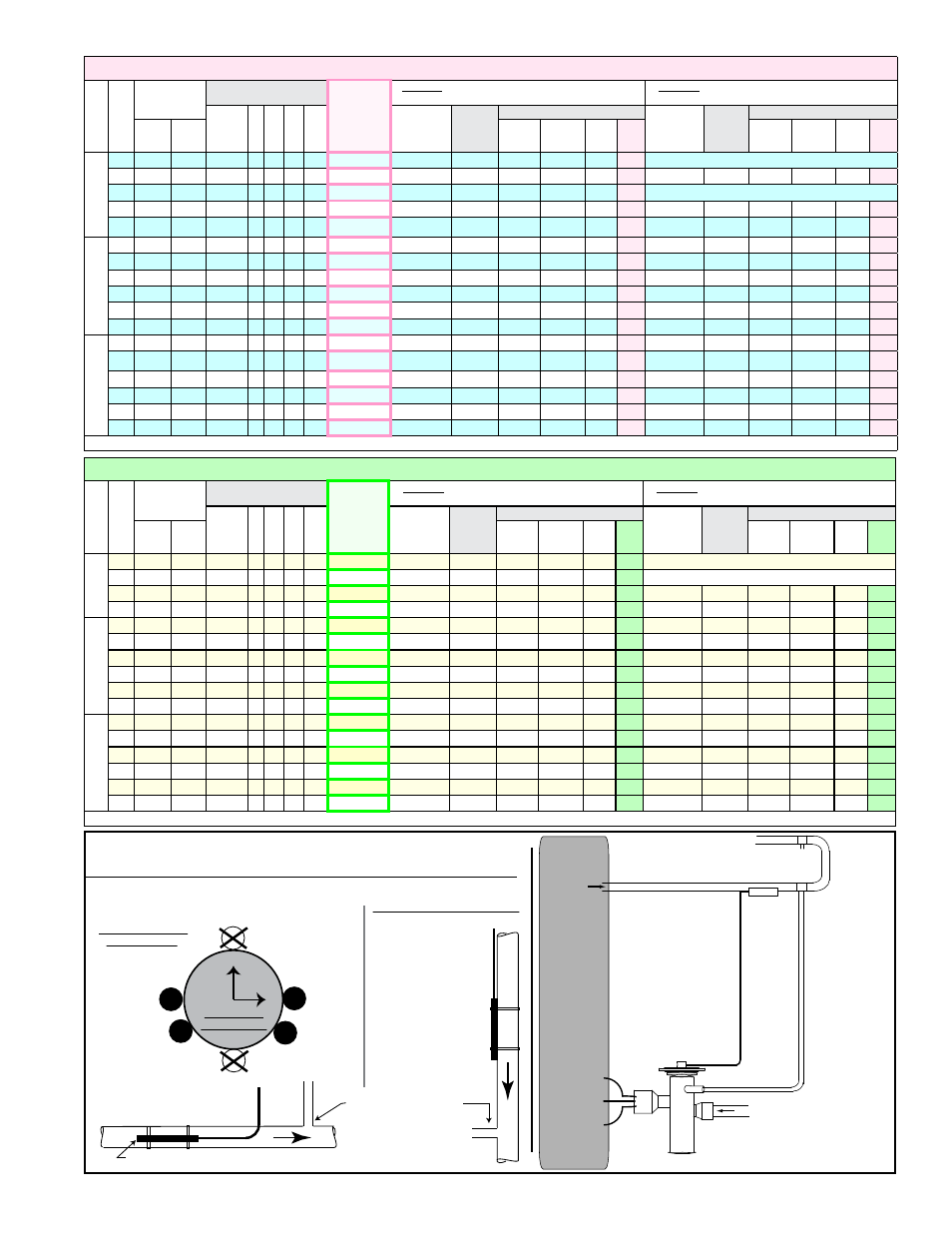
Bulb at
3 o’clock
Bulb at
4 o’clock
Bulb at
8 o’clock
Bulb at
9 o’clock
12
3
6
9
Position bulb flat against the surface of the suction line tubing. Secure bulb
tightly and insulate.
Suction Line
Cross Section
Suction Line
Thermostatic Expansion Valve Bulb
Suction Line
Thermostatic
Expansion
Valve Bulb
(Capillary tube should
be out the top.)
Horizontal Section
of Suction Line
(preferred location)
Vertical Section of Suction Line
(descending flow only)
Capillary
tubing
from TEV
Capillary tubing from TEV
Connect field-supplied
equalizer tubing from
the TEV into the
suction line a short
distance downstream
of the bulb.
External equalizer
line requires field-
supplied tubing
from the 1/4” ODF
fitting on the valve
and connected
into the suction
line preferably at
location “X” down-
stream of the
TEV bulb. If “X” is
not possible,
location “Y” is
acceptable as long
as pressure is
essentially the
same as at “X”.
Thermostatic
Expansion
Valve (TEV)
Evaporator Coil in Model
ACU or Option C
Cased Cooling Coil
TEV Bulb
Suction Line
X
Y
Follow the manufacturer’s instructions to install the TEV. Bulb
placement and equalizer line installation are illustrated here.