Warning, Temp rise: δ t= (btu/h)/(cfm*1.08) – Reznor Q6SD Option - Installation - Elec Heating User Manual
Page 4
4
Breaker Attachment
Install the circuit breaker mounting rail to the control panel
with the 4 blunt tip screws provided.
Attaching to Bracket
Attach the circuit breakers in the unit by hooking the
bottom in the base of the circuit breaker onto the left rail
of the bracket and rotating to the right. The circuit breaker
should snap into place. Install the breakers so that the
ON position is to the right. See Figure 2 (page 5) for
component location.
Breaker Removal
Insert a screwdriver into the hole in the release tab and
pull out while rotating the breaker out and to the left. The
white release tab is located at the base of the breaker
under the line side (right) terminals.
Single Circuit Kit (single phase only)
Refer to the instructions included with the single circuit
adapter kit for details on how to configure the adapter.
Install the adapter as shown in the instructions in the
line side (right) of the breakers. Proceed to the Element
Installation section.
Terminal Blocks
Approved H3HK heater kits are shipped with a terminal
block for small package units. For large package units the
terminal block(s) supplied with the kits will not be used.
The electric heater kits will be wired to the existing factory
installed terminal block. If the number of circuits indicated
in Tables 3 - 8 (pages 6 - 9) is 2 or 3, then the circuit
breakers must be used. See Circuit Breakers (page 3).
Staged Heat
To stage the heat on the 15 kw or 20 kw Heater Kits the
factory set wiring will need to be modified. The orange
wire in Pin 2 on the Heat Accessory Plug will be re-routed.
See the Installation Instructions supplied with the HP or
AC for typical thermostat connections.
WARNING:
Rooftop applications with vertical ducts must
have an elbow installed in the supply duct so that
the elements are not directly over a supply grille.
WARNING:
The heater will not function properly if the
elements are not correctly installed.
Element Installation
Remove the blower access panel. Remove the heater
close-off plate(s) in the electric heat panel. When installing
single banks of heaters, position them closest to the blower.
Install the heater kit in the opening with the limit control
towards the top of the unit if the unit is using the side
supply and return duct openings. If the unit is using the
Element Power Wiring
Route the main power leads (heavy black & red wires) and
the 9 or 12-pin heat plug through the access hole at the
top of the control panel to the circuit breaker or terminal
block. Connect the 9 or 12-pin heat kit plug to the heat
accessory plug located in the control box. Refer to the
detailed wiring diagrams (pages 21 - 30) for connections.
Make sure that the connections are secure. Select large
package units have additional terminal blocks installed.
The power leads from the heater kit should be attached
to these terminal blocks. Wires needed to connect from
terminal blocks to circuit breakers should be field supplied.
The 6 inch leads are provided with the heater kit to connect
the circuit breaker(s) to the compressor contactor.
Mark
the appropriate box on the unit rating plate with an “X” to
indicate which heater kit has been installed.
IMPORTANT: Torque the circuit breaker lugs to 45 in-lbs.
AIRFLOW
All heater kit temperature rise data in See Tables 27 - 40
(pages 31 - 39) have been calculated using 10kW heaters
(9kW for 3 phase units). For other sized heater kits, use
the following steps below to determine the heat rise for
your particular heater kit.
1. Determine your CFM. NOTE: This data is found by
locating your blower motor tap settings in the data
supplied with the Installation Instructions. See Tables
25 - 36.
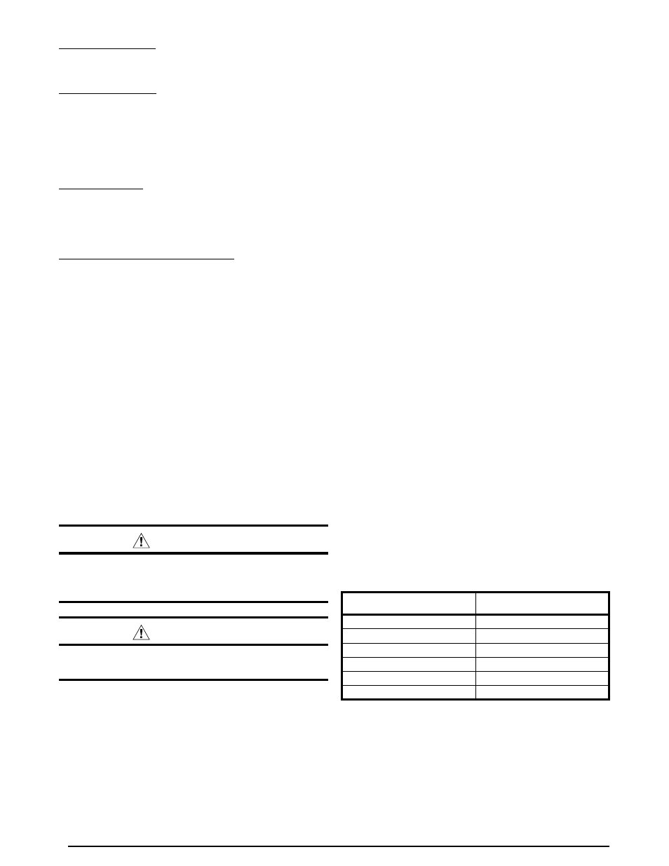
2. Locate your heater kits kW value and Btu/h in Table 2.
3. Input the values into the following equation:
Temp Rise:
Δ
T= (Btu/h)/(CFM*1.08)
NOTE: Generally the heat rise should be 30 - 40 degrees.
Anything above 40 degrees should be avoided.
downshot supply and return openings, install the heater
kit in the opening with the limit towards the bottom of
the unit. See Figure 3 (page 5). NOTE: Make sure the
element support rod is inserted into the support bracket.
Fasten the heater with the same screws used to secure
the close-off plates.
KW/h
Btu/h
5
17,060
8
27,297
9
30,709
10
34,121
15
51,182
20
68,242
Table 2. kW & Btu/h Ratings