Reznor Q6SD Option - Installation - Elec Heating User Manual
Page 34
34
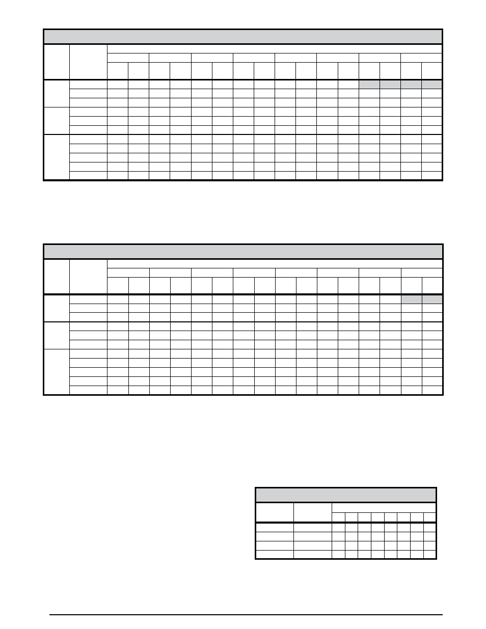
P6SD SERIES - SINGLE PHASE
UNIT
BLOWER
SETTING
External Static Pressure Drop - inches water column
0.1
0.2
0.3
0.4
0.5
0.6
0.7
0.8
CFM
HEAT
RISE
CFM
HEAT
RISE
CFM
HEAT
RISE
CFM
HEAT
RISE
CFM
HEAT
RISE
CFM
HEAT
RISE
CFM
HEAT
RISE
CFM
HEAT
RISE
X36
Low*
1153
27
1102
29
1043
30
990
32
912
35
831
38
731
43
618
51
Medium
1367
23
1320
24
1271
25
1205
26
1138
28
1065
30
968
33
845
37
High
1610
20
1562
20
1504
21
1442
22
1365
23
1295
24
1214
26
1109
28
X48
Low*
1584
20
1568
20
1532
21
1489
21
1445
22
1387
23
1322
24
1236
26
Medium
2026
16
1982
16
1935
16
1889
17
1822
17
1744
18
1660
19
1554
20
High
2361
13
2278
14
2218
14
2141
15
2066
15
1976
16
1870
17
1758
18
X60
Tap T1
1515
21
1450
22
1380
23
1350
23
1280
25
1250
25
1200
26
1160
27
Tap T2**
1580
20
1520
21
1460
22
1400
23
1300
24
1280
25
1260
25
1230
26
Tap T3*
1740
18
1690
19
1650
19
1600
20
1360
23
1500
21
1460
22
1390
23
Tap T4
1960
16
1910
17
1840
17
1820
17
1540
21
1740
18
1700
19
1600
20
Tap T5
2090
15
2050
15
2010
16
1975
16
1780
18
1900
17
1850
17
1790
18
NOTES:
Calculated values in matrix are all with 10KW for 1 phase
Temperature rises shaded gray are for reference only. These conditions are not recommended.
* Denotes factory set cooling speed
** Denotes factory set electric heating speed
Table 32. P6SD Series Blower Data - (Single Phase)
P6SD SERIES - 3 PHASE
UNIT
BLOWER
SETTING
External Static Pressure Drop - inches water column
0.1
0.2
0.3
0.4
0.5
0.6
0.7
0.8
CFM
HEAT
RISE
CFM
HEAT
RISE
CFM
HEAT
RISE
CFM
HEAT
RISE
CFM
HEAT
RISE
CFM
HEAT
RISE
CFM
HEAT
RISE
CFM
HEAT
RISE
X36
Low*
1153
25
1102
26
1043
27
990
29
912
31
831
34
731
39
618
46
Medium
1367
21
1320
22
1271
22
1205
24
1138
25
1065
27
968
29
845
34
High
1610
18
1562
18
1504
19
1442
20
1365
21
1295
22
1214
23
1109
26
X48
Low*
1584
18
1568
18
1532
19
1489
19
1445
20
1387
21
1322
22
1236
23
Medium
2026
14
1982
14
1935
15
1889
15
1822
16
1744
16
1660
17
1554
18
High
2361
12
2278
12
2218
13
2141
13
2066
14
1976
14
1870
15
1758
16
X60
Tap T1
1515
19
1450
20
1380
21
1350
21
1280
22
1250
23
1200
24
1160
25
Tap T2**
1580
18
1520
19
1460
19
1400
20
1300
22
1280
22
1260
23
1230
23
Tap T3*
1740
16
1690
17
1650
17
1600
18
1360
21
1500
19
1460
19
1390
20
Tap T4
1960
15
1910
15
1840
15
1820
16
1540
18
1740
16
1700
17
1600
18
Tap T5
2090
14
2050
14
2010
14
1975
14
1780
16
1900
15
1850
15
1790
16
NOTES:
Calculated values in matrix are all with 9KW for 3 phase
Temperature rises shaded gray are for reference only. These conditions are not recommended.
* Denotes factory set cooling speed
** Denotes factory set electric heating speed
Table 33. P6SD Series Blower Data - (3 Phase)
Q4SE & PPH1SE
Nominal
KW
CFM
Switch Number
1
2
3
4
5
6
7
8
0-5
500
0
0
6-10
700
1
0
11-15
900
0
1
16-20
1100
1
1
NOTE: 1-ON, 0=OFF
Table 34. Q4SE/PPH1SE Series Minimum
Electric Heat Airflow - (all models)