Wiring dia gram, Electrical information, Cc 1 – Reznor R6GN Unit Installation Manual User Manual
Page 30: Ibc ofc, Cc 2
30
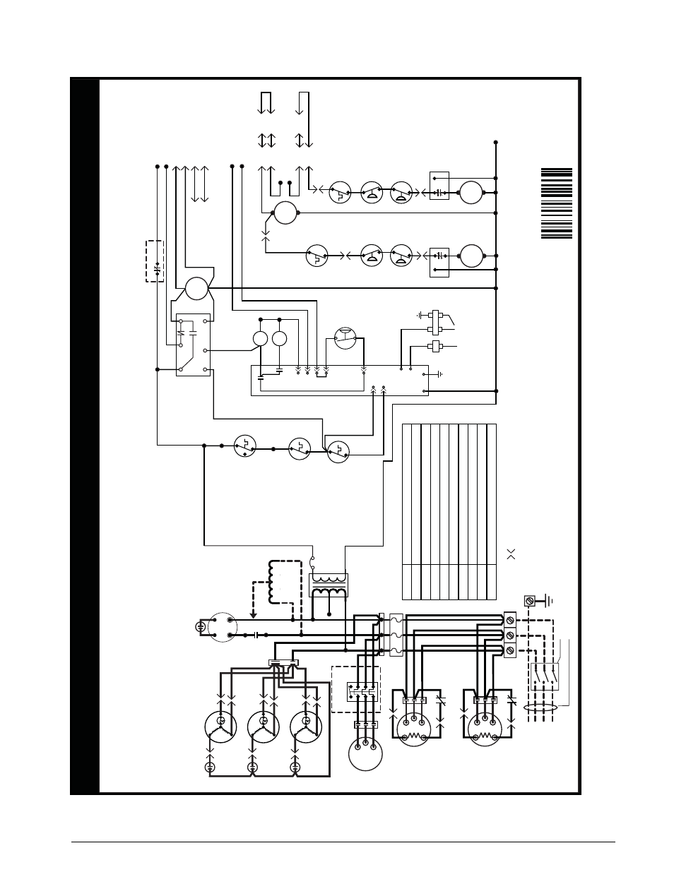
ElEctRIcal INFoRMatIoN
Figure 15. Ladder Diagram - 150/180 Series
WIRING DIA
GRAM
NO
TES:
1.
Couper le courant
av
ant de faire letretien.
2.
Empl
oy
ez uniquement des conducteur
s en cuivr
e.
R6GN-150*/180* Series Co
nv
er
tible
Pa
ck
ag
e Gas Heat/Electric Air Conditioner
1.
Disconnect all po
wer bef
ore servicing.
2.
For suppl
y connections use copper conductor
s onl
y.
3.
If an
y of the original wire as supplied with the furnace
mu
st be replaced
, it m
ust
be replaced with wiring material ha
ving a temperature rating of at least 105C.
4.
For supp
ly
wire ampacities and
ov
er
current pr
otection
, see unit rating label
.
5.
Remo
ve white wire fr
om PO
WER BLOCK- L3 and connect to autotransf
ormer red wire
.
6.
For 120C Models on
ly
. For 208V operation remo
ve wire fr
om 230V tap an
d
place on 208V tap.
Three Phase 60 Hz.
208-230/460
Volt
710849A
01/11
(Replaces 7108490)
Field Supplied Disconnect (3Phase
Po
wer Only
)
Fo
r supply connections use copper conductors onl
y.
Unit
Te
rm
inal
Bloc
k
T2
T3
T1
IB
C
Indoor Bl
ow
er Motor
L1
L2
L3
GN
D
FUSE
BLOCK
1
2
3
BK
WH
INDUCE
R
MO
TO
R
BO
R
Tr
ansf
or
mer
See Note
6
Au
totransf
or
mer
460V
Units Only
RE
D
See Note
5
L3
L2
RD/WH BK
LV
T-C (24V COM.)
CC
1
24V Ho
t
Max
Temp
.
Limi
t
24V Common
Flame
Rollout
Switch
Upper
Seconda
ry
Limi
t
IBC
OFC
2
3
1
2
3
1
CC
2
CLOR1
(Field
Installed
Option
)
Stage
1
Ev
ap
.
Freez
esta
t
Lo
w
Pressure
Switc
h
High
Pressure
Switc
h
CLOR2
(Field
Installed
Option
)
E-5
E-4
LV
T-Y1 (Stage 1 Cool)
LV
T-Y2 (Stage 2 Cool)
E-2
E-1
LV
T-W1 (Stage 1 Heat)
LV
T-W2 (Stage 2 Heat)
E-8
E-15
E-14
BOR
95
96
LV
T-
G
LV
T-
R
E-9
To
Mix
ed Air Sensor
(When Econ Used)
TDR -
Time Dela
y Rel
ay
IBC - Contactor
, Indoor Blo
wer Motor
CC1&2 - Contactor
, Stage 1&2 Compressor
OFC - Contactor
, Outdoor
Fa
n
CCH - Crankcase Heaters
, Stage 1&2 Compressor
LV
T - Lo
w
Vo
ltage
Te
rm
inal
BR - Blo
wer Rela
y
CLOR1 & 2 - Compressor Lo
ck
out Rela
y
BOR - Bl
ow
er Ov
er
load Rela
y
TB -
Te
rm
inal Board - HX
S
S
S
C
C
C
R
R
R
Compressor 2
T2
T1
T3
CC
2
CC
2
SC-4
SC-5
Compressor 1
T2
T1
T3
CC
1
CC
1
SC-4
SC-5
Outdoor
Fan Moto
r
Outdoor
Fan Moto
r
Outdoor
Fan Moto
r
BK
WH
C1-3
C1-1
C1-2
C2-3
C2-1
C2-2
C1-3
C1-1
C1-2
E-4
E-2
E-1
Stage
2
Ev
ap
.
Freez
esta
t
Lo
w
Pressure
Switc
h
High
Pressure
Switc
h
SC-1
SC-1
SC-2
SC-2
E-3
PO
WER BLOCK
P1-2
P1-8
P1-3
P2-3
K2
S1
S2
IGNITION
CONTR
OL
G
C
R
L
COM
NC
NO
BLO
WE
R
TIM
E
DEL
AY
K1
P2-4
W1
W2
HV
TRANSFORMER
FS
P2-1
COM
P1-9
P1-6
TB-3
TB-2
GAS
VA
LV
E
PRESSURE
SWITCH
SP
ARK
IGNI
TO
R
FLAME
SENSOR
IC-L1
IC-IND
IC-K
4
GND
High Limit Input
Rollout Switch Input
C
230V
208V
95
96
- Indicates plug connection.
Letter Indicates which plug.
Number indicates pin location.
E - Economi
ze
r
SC - Saf
ety Circui
t
IC - Ignititon Control
Status Light
(Red)
Ignition Control
Fa
ilure Code
Steady On
2 flashes
Operation Nor
mal
3 flashes
4 flashes
5 flashes
6 flashes
7 flashes
8 flashes
9 flashes
10 flashes
Pressure/cent
rifugal
sw
itch open with inducer on
Loc
kout from too man
y
fa
iled ignition tr
ie
s
Loc
kout from too man
y flame losses
High temperature
sw
itch open
Rollout
sw
itch open
Flame present with gas off`
Exceeded max limit tr
ips in one call
fo
r heat (5)
Gas
Va
lv
e
Fa
ul
t
Pressure/cent
rifugal
sw
itch closed with inducer of
f
4A
OPTIONAL
OPTIONA
L