Component functions, Troubleshooting – Reznor R6GN Unit Installation Manual User Manual
Page 22
22
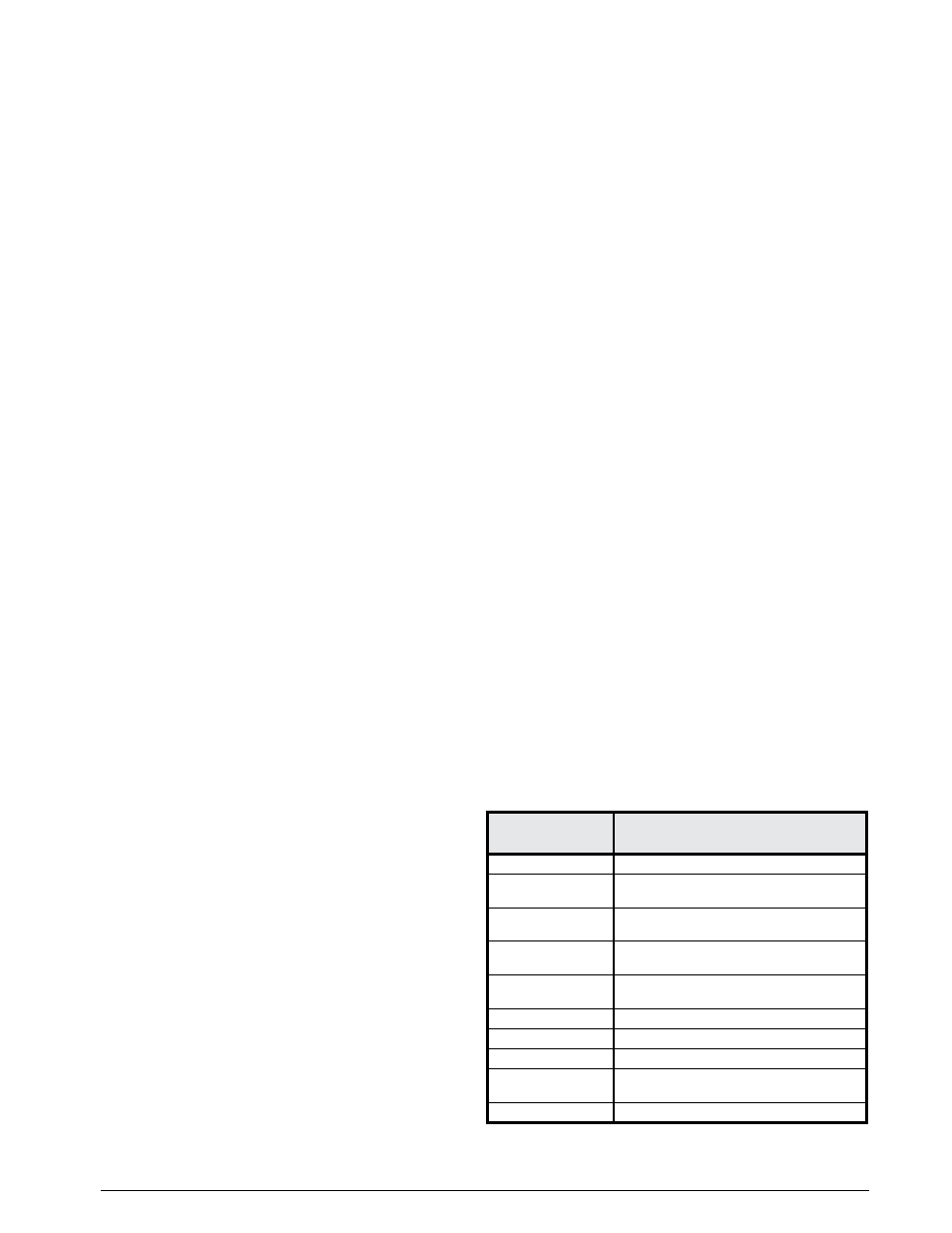
Table 2. Diagnostic Codes
StatuS lIGHt
(Red LED)
Fault
coNDItIoN
Continuous ON
Operation Normal
2 Flashes
Pressure/centrifugal switch open
with inducer on
3 Flashes
Pressure/centrifugal switch closed
with inducer off
4 Flashes
Lockout from too many
failed ignition tries
5 Flashes
Lockout from too many
flame losses
6 Flashes
High temperature switch open
7 Flashes
Rollout switch open
8 Flashes
Flame present with gas off
9 Flashes
Exceeded max limit trips (5)
in one call for heat
10 Flashes
Gas valve fault
Refrigerant High Pressure Switch - This factory installed
switch is designed to de-energize the unit when excessive
pressure occurs due to abnormal conditions. Under normal
conditions, the switch is closed. If the discharge pressure
rises above 650 psig, then the switch will open and de-
energize the outdoor unit. The switch is a manually reset
type and will remain open until the button on top of the
switch is depressed.
Upper Secondary Over-Temperature Limit - The upper
secondary limit control acts to prevent the unit from
operating in case the indoor airflow is disrupted for any
reason. (example: Indoor motor failure, broken belt, etc).
If the limit opens, the 24V input signal to the L terminal of
the blower time delay relay is lost. The relay switches to
Normally Closed (NC) and remains in that position until
the limit closes. The upper secondary limit is located on the
blower deck side panel, opposite end to the motor drive,
and can be accessed through the blower/heat exchanger
access panel for inspection or service.
coMPoNENt FuNctIoNS
The descriptions below are various functional components
that affect the operation and shutting down of this unit.
Some of these components and their locations are shown in
Figure 11 (page 23). If any component on this unit must be
replaced, use only Nordyne authorized replacement parts
specified in the Replacement Parts List provided online.
Flame Roll-Out Control - The flame roll-out control acts
to verify that the burner flame is being drawn into the heat
exchanger tubes. If the burner flame is not being drawn
into the heat exchanger tubes, the roll-out control will
open within several seconds. The combustion blower will
continue to operate if the flame roll-out control opens until
it is manually reset.
Flame Sensor - The flame sensor acts to prove that flame
has carried over from the ignitor to the right-most burner. If
no flame is sensed, the unit will be shut down automatically
and attempt fourteen additional ignition trials before going
into lockout. Recovery from lockout requires a manual
reset by either resetting the thermostat or removing 24
volts for a period of 5 seconds. If the thermostat is still
calling for heat after one hour the control will automatically
reset and attempt to ignite the burner again.
Gas Valve - The gas valve controls the flow of gas to
the burners in both low and high fire. When the valve is
energized, it automatically opens and regulates the gas
pressure to the manifold.
Inducer Motor Pressure Switch - This pressure switch
acts to verify that the inducer motor is running. Combustion
gases are drawn through the heat exchanger tubes and
vented through the vent system.
Indoor Coil Freeze Protection Thermostats - The freeze
protection switches are designed to protect the indoor
coils from ice and frost accumulations in the event of a
loss of airflow by preventing the liquid refrigerant from
reaching the compressors. During normal operation, the
switches are closed and will open if the coil temperature
reaches 28° F (-2° C). The switches will close if the coil
temperature reaches 57° F (12° C).
Over-Temperature Limit Control - The over-temperature
limit control acts to prevent the air temperature leaving the
unit from exceeding the maximum outlet air temperature.
If the limit opens, the 24V input signal to the L terminal of
the blower time delay relay is lost. The relay switches to
Normally Closed (NC) and remains in that position until
the limit closes. The over-temperature limit is located
beneath the heat exchanger tubes (hairpin end) and can
be accessed through the blower/heat exchanger access
panel for inspection or service.
Refrigerant Low Pressure Switch - This factory installed
switch is designed to protect the compressor from a loss
of charge. Under normal conditions, the switch is closed.
If the suction pressure falls below 5 psig, then the switch
will open and de-energize the outdoor unit. The switch
will close again once the suction pressure increases
above 20 psig.
tRouBlESHootING
If the unit does not operate properly in the cooling mode,
check the following:
• The thermostat is operating properly.
• Electrical power to the unit is turned on.
• All safety switches are closed.
• The service doors are in place.
• Transformer circuit breaker is reset.
If the unit does not operate properly in the heating mode,
check the following:
• The thermostat is operating properly.
• Electrical power to the unit is turned on.
• All safety switches are closed.
• The gas is on and shut-off valve is open.
• The service doors are in place.
• The flame roll-out control is closed.
• Refer to the diagnostic codes in Table 2 below or the
wiring diagram (Figure 15, page 30).
• Transformer circuit breaker is reset.