7 hydraulic installation, 1 valve assembly, 1 dual acting assembly – NORAC UC4+BC+AN2 User Manual
Page 27
24
4.7
H
YDRAULIC
I
NSTALLATION
WARNING!
The hydraulic system creates very
high pressure. Before disconnecting
any hydraulic lines ensure all pressure
has been bled from the system.
When changing the boom hydraulic
hoses leave the booms in
TRANSPORT POSITION.
NORAC provides proportional hydraulic
valves for sprayer boom applications. For
the generic installation kit, the customer
must supply all hoses and fittings required.
The fittings (Item F07) on the NORAC
valve block are #6 MB (male ORB) to #6 MJ
(male JIC). You will need the mating female
JIC fitting on your hoses. If an adapter is
required, add it after the JIC portion of
these fittings. For a typical hydraulic layout,
refer to the installation instructions and
Figure 4 and Figure 7.
IMPORTANT:
Component failure due to oil
contamination is not covered under
the UC4+ Spray Height Control
system warranty. It is recommended
that a qualified technician does the
hydraulic installation.
4.7.1 Valve Assembly
1. On a clean surface remove all plastic
plugs from the NORAC hydraulic Valve
(V01) (Figure 26).
2. Install the 6MB-6MJ fittings (F07) on the
"P" and "T" ports and tighten to 18 ft-
lbs.
Figure 26: NORAC Valve Block
3. At this point the sprayer hydraulic
system must be identified as being single
acting or dual acting.
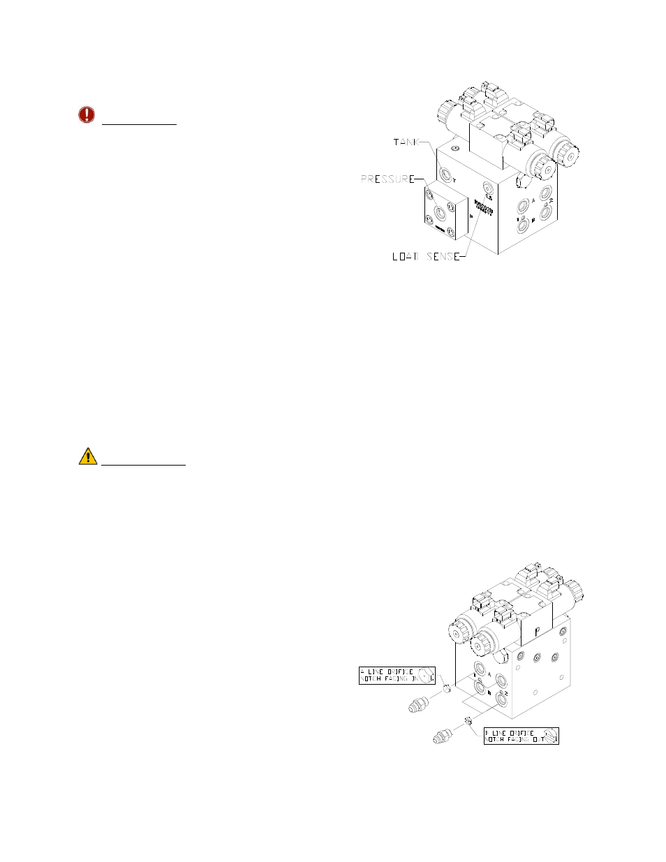
4.7.1.1 Dual Acting Assembly
1. Install the orifices (F08) into the "B"
ports with the notch facing outward
as shown in Figure 27.
2. Install the orifices (F08) into the "A"
ports with the notch facing inward
as shown in Figure 27.
3. Install the 6MB-4MJ fittings (F07) into
the "A" and "B" ports and tighten to 18
ft-lbs.
Figure 27: Dual Acting Valve Block