Aligning internal magnetometer, 7430‐0808‐01 rev. b, Gnav540 user manual – Moog Crossbow GNAV540 User Manual
Page 58: Alignment instructions, Figure 21 internal magnetometer alignment dialog
greater than the values specified on the data sheet or fluctuating heading performance may indicate magnetic field
disturbances near the unit.
NOTE: An acceptable calibration will provide X and Y Hard Iron Offset Values of <0.1 and a Soft Iron Ratio >0.95. If
this procedure generates calibration parameters significantly outside of this range, the system will assert the
softwareErrorÆdataErrorÆmagAlignOutOfBounds error flag. Refer to Chapter 11. Built In Test (BIT)) for
details about error flag handling.
For more information about magnetic fields and the effects on readings and alignment, refer to Chapter 4.
Magnetometer Calibration and Alignment Guidelines on page 39.
Alignment Instructions
structions using NAV‐VIEW 2.2.
wing are the magnetometer alignment in
• Aligning Internal Magnetometer, page 58
• Aligning External Magnetometer, page 59
Aligning Internal Magnetometer
1. Ensure the unit is configured to use the internal
page 56.
magnetometer. Refer to
ced on
2. On the menu bar (see Figure 8), click
Configuration and then select Magnetometer
Alignment from the drop menu.
60 degree turn can b
within
onds, check AutoTe
3. If the 3
e completed
120 sec
rminate.
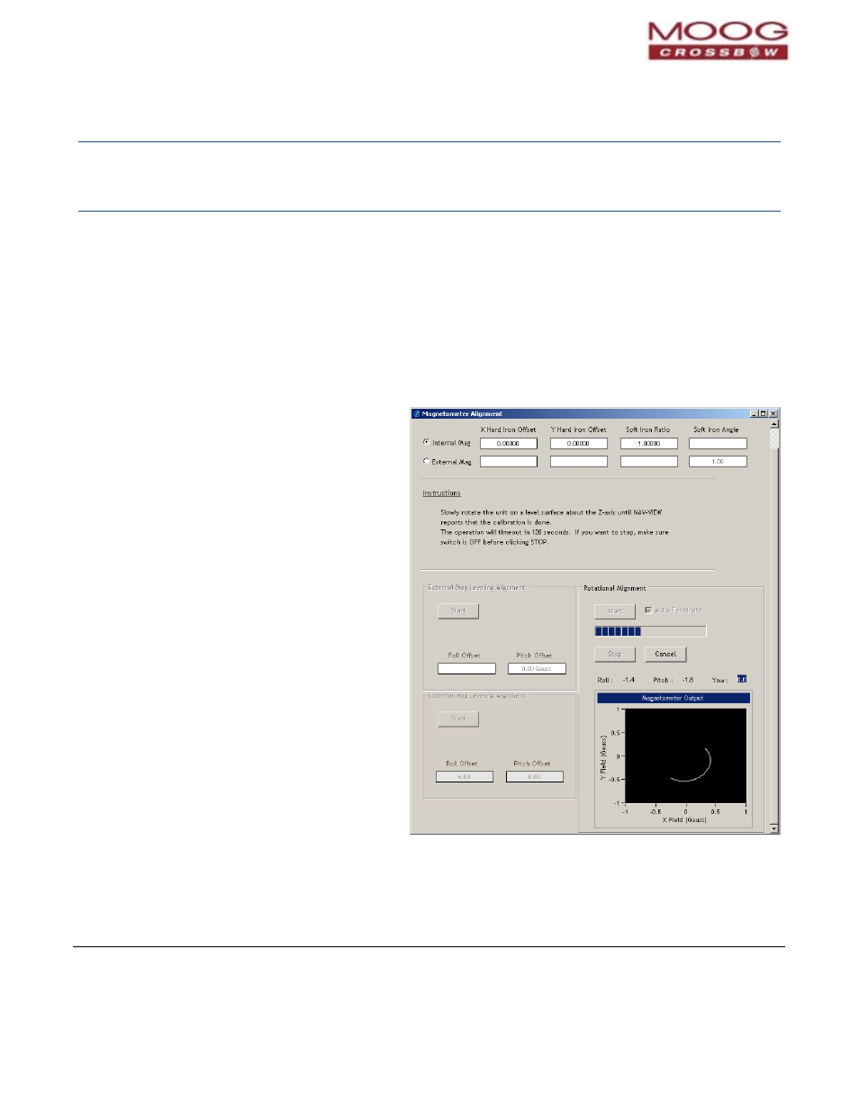
4. Under Rotational Alignment, select the Start
button to begin the alignment. Follow the
instructions displayed in the screen. Refer to
Figure 21.
5. Rotate the GNAV540 for 380 degrees of rotation
or until the message is displayed that alignment
is complete.
Figure 21 Internal Magnetometer Alignment Dialog
Page 58
GNAV540 User Manual
7430‐0808‐01 Rev. B