2 powering the ev kit board, 3 basic connection setup, Powering the ev kit board – Maxim Integrated MAX78630+PPM Evaluation Kit User Manual
Page 8: Basic connection setup, Figure 2: max78630+ppm ev board connections
MAX78630+PPM Evaluation Kit User Manual
8
Rev 0
2.2 Powering the EV Kit Board
The MAX78630+PPM EV board is normally powered through the USB port (J21).If power needs to be supplied
from a different source, a 5V DC can be applied to the connector J16; see
When the MAX78630+PPM EV board is powered through via USB, the same cable also provides the
communications link between the host PC and the MAX78630+PPM EV board.
2.3 Basic Connection Setup
This section shows examples of basic connections between the MAX78630+PPM EV board and external
equipment. Additional connection examples can be seen in the MAX78630+PPM IC data sheet. Note that this
board does not directly support voltage transformers (VT) and provides a shunt resistor as alternative to the
current transformer on phase C.
The following examples are only a subset of all possible measurement configurations. Refer to the
MAX78630+PPM IC data sheet for configurations and system connection diagrams.
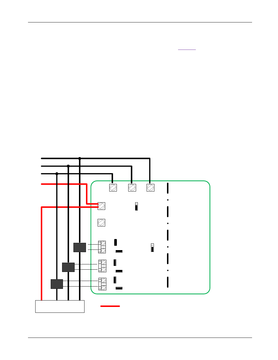
2.3.1 Wye-Connected or 3V Delta-Connected Three-Phase Systems
For Wye-connected systems, all three-phase (Line-to-Neutral) voltages are measured. The Neutral line is the
reference for all voltages (V3P3A). Jumper J11 must be in position 2-3 (3V Wye/Delta). It is also possible to
directly measure all three voltages in a Delta configuration. In that case, the Neutral is not accessible and the
MAX78630+PPM EV board is at a virtual center potential.
V1
V2
V3
Nin
Nout
I1
J39
I2
J40
I3
J41
J5
J4
J3
J2
J1
J
13
J
19
J
42
J
15
J11
MAX78630EVAL V1
J14
J20
J43
CT1
CT2
CT3
LOAD
A
B
C
N
A
B
C
N
Neutral Connection for Wye Configurations
Figure 2: MAX78630+PPM EV Board Connections