3 serial interfaces selection and configuration, 1 uart interface settings, Serial interfaces selection and configuration – Maxim Integrated MAX78630+PPM Evaluation Kit User Manual
Page 14: Uart interface settings, Table 9: sw4 serial interface selection, Table 10: sw5 address selection, Table 11: jumper setting for uart/usb interface
MAX78630+PPM Evaluation Kit User Manual
14
Rev 0
3 Serial Interfaces Selection and Configuration
The MAX78630+PPM has integrated UART, SPI (Slave), and I
2
C (Slave) interfaces. Only one interface can be
active at a time and the selection is done at reset/power-on.
The UART interface also supports RS-485/422. The MAX78M6630+PPM EV board includes an isolated RS-
485/422 transceiver.
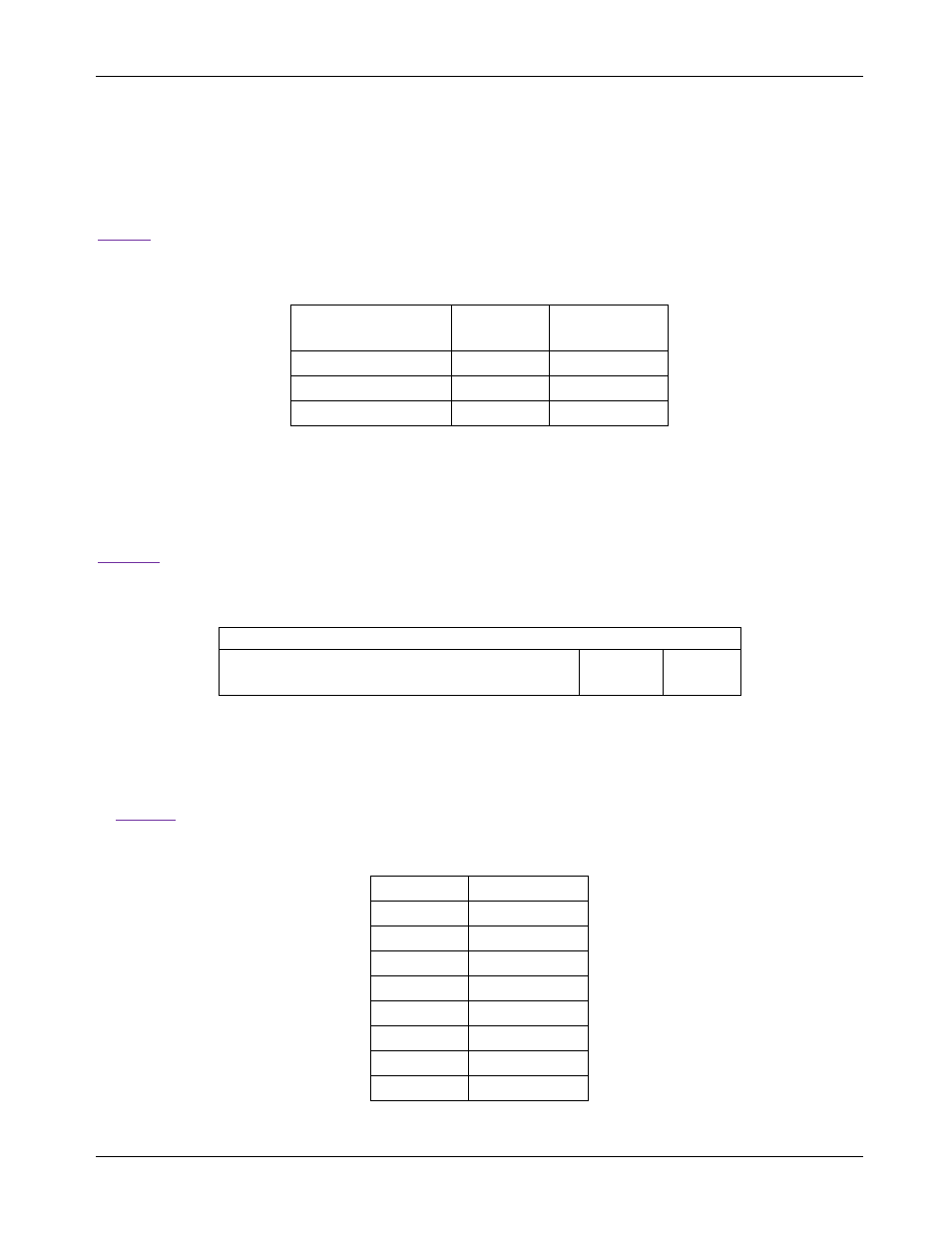
shows the settings of SW4 for the individual interface selection; the signal IFC0 and IFC1 are sampled
at reset and power-on.
Table 9: SW4 Serial Interface Selection
Interface Mode
SW4 1
(IFC0)
SW4 2
(IFC1)
SPI
0 (ON)
X (don’t care)
UART
1 (OFF)
0 (ON)
I
2
C
1 ()FF)
1 (OFF)
The MAX78630+PPM EV board provides the serial port signals on connector J16.
3.1 UART Interface Settings
The MAX78M6630+PPM implements a serial communication protocol (SSI) that supports multipoint
communication. The device address (lower bits) is selected through the pins ADDR0 and ADDR1, as shown in
. The upper bits of the address are set through the register DEVADDR, as described in the IC data
sheet.
Table 10: SW5 Address Selection
Device Address
DEVADDR[5:1]
SW5 2
Bit 1
SW5 1
Bit 0
The EV board includes an isolated RS-485/422 transceiver. The MAX78630+PPM serial UART is connected to
the RS-485/422 transceiver when a multi-drop RS-485/422 bus is available.
UART/USB Interface and UART/RS-485/422 Interface Configuration
In order to operate the UART through the USB/FTDI device or RS-485/422, the jumper must be set according
to
Table 11: Jumper Setting for UART/USB Interface
Jumper
Position
J17
1-2
J18
1-2
J28
Removed
J29
Removed
J27
Removed
J38
Removed
J30
Removed
J12
Removed