2 spi settings, Spi settings, Table 12: jumpers settings for uart/rs-485/422 – Maxim Integrated MAX78630+PPM Evaluation Kit User Manual
Page 15: Table 13: j22 rs-485/422 connector pin assignment, Table 14: jumper setting for spi/usb interface
MAX78630+PPM Evaluation Kit User Manual
Rev 0
15
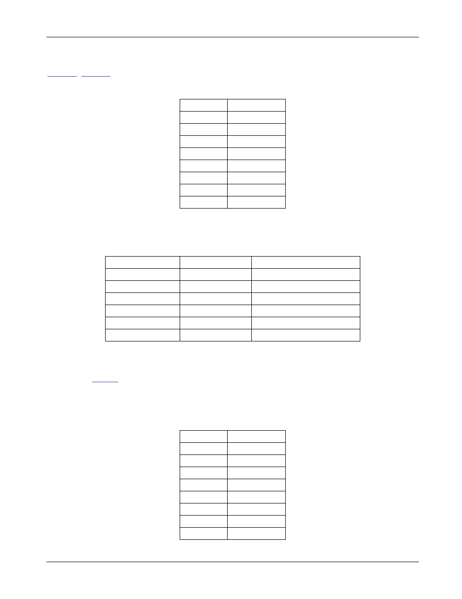
UART/RS-485/422 Interface Configuration
In order to operate the UART through the RS-485/422 transceiver, the jumpers must be set accordingly to
contains the pin assignment of connector J22.
Table 12: Jumpers Settings for UART/RS-485/422
Jumper
Position
J17
2-3
J18
2-3
J28
Removed
J29
Removed
J27
(See note)
J38
(See note)
J30
Removed
J12
2-3
Note:
These jumpers are used to insert a 120Ω termination on the RS-485 bus. The termination should be
inserted or removed according to the board location on the RS-485 bus.
Table 13: J22 RS-485/422 Connector Pin Assignment
J22 Pin Number
Pin Name
Pin Description
1
+5V DC
Connect to external source
2
Data In – P
Three-state, bidirectional
3
Data In – N
Three-state, bidirectional
4
Data Out – N
Three-state, bidirectional
5
Data Out – P
Three-state, bidirectional
6
GND
Connect to external source
3.2 SPI Settings
The MAX78M6630+PPM has an on-chip SPI (slave) interface. The interface is selected through SW4
according to
. The SPI interface can be accessed through the USB interface or directly via J16; both
connectors are galvanically isolated.
SPI/USB Interface Configuration
Table 14: Jumper Setting for SPI/USB Interface
Jumper
Position
J17
1-2
J18
1-2
J28
Inserted
J29
Inserted
J27
Removed
J38
Removed
J30
Inserted
J12
1-2