Fig. 5 — frame 6 drive components, Fig. 6 — frame 7 drive components – Carrier 19XRV User Manual
Page 4
4
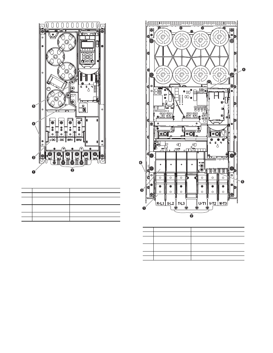
LEGEND
Fig. 5 — Frame 6 Drive Components
NO.
NAME
DESCRIPTION
1
Power Terminals
R/L1, S/L2, T/L3, U/T1, V/T2, W/T3
2
PE Grounding Studs
Terminating point to chassis ground
for incoming motor shield
3
DC Bus and Brake
Terminals
+DC, -DC, BR1, BR2
4
PE-A and PE-B
MOV and CMC Jumper Wires
5
DC+ and DC-
Bus Voltage Test Points
A19-
1832
LEGEND
Fig. 6 — Frame 7 Drive Components
NO.
NAME
DESCRIPTION
1
Power Terminals
R/L1, S/L2, T/L3, U/T1, V/T2, W/T3
2
PE Grounding Studs
Terminating point to chassis ground
for incoming motor shield
3
DC Bus and Brake
Terminals
+DC, -DC, BR1, BR2
4
PE-A and PE-B
MOV and CMC Jumper Wires
5
DC+ and DC-
Bus Voltage Test Points
A19-1833
See also other documents in the category Carrier Conditioners:
- 42S (72 pages)
- 30GT (4 pages)
- 48SS060 (8 pages)
- 50ME (54 pages)
- 38AH024-034 (26 pages)
- ZC (28 pages)
- 30GA (12 pages)
- COMFORTLINK 48A2 (8 pages)
- 48HE003---006 (64 pages)
- 33ZCSECTRM (52 pages)
- MODU-PAC 50DF (37 pages)
- 17DA (8 pages)
- SINGLE PACKAGED ELECTRIC COOLING UNITS 50GS (28 pages)
- 48JZ (N) 024-060 (30 pages)
- 30GX080-176 (8 pages)
- 50DL (24 pages)
- 50GL-A (4 pages)
- NP034-074 (72 pages)
- 40GXQ (12 pages)
- 30XA080-500 (8 pages)
- 39E (12 pages)
- 40KMQ------301 (10 pages)
- 38AE (12 pages)
- 48AW (118 pages)
- 38GXQ (28 pages)
- 48ES---A (38 pages)
- 48GL (22 pages)
- 48GH (22 pages)
- 40QA024-060 (24 pages)
- TJF004 (52 pages)
- 39LD (40 pages)
- 48DL (4 pages)
- 48/50TC04---28 (44 pages)
- 50EJ (56 pages)
- 17EX (120 pages)
- 50BA (24 pages)
- 50BB (16 pages)
- 50BB (8 pages)
- 50BJ (20 pages)
- 30H (16 pages)
- 48HJD005-007 (48 pages)
- 50ZP (6 pages)
- 50DP016 (16 pages)
- 50LJ008-014 (19 pages)