Carrier 19XRV User Manual
Page 31
31
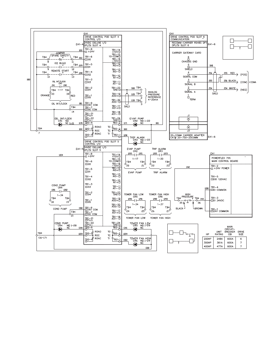
APPENDIX A — WIRING SCHEMATICS (cont)
ROCKWELL POWERFLEX 755 WIRING SCHEMATIC (Typical) (cont)
34
34
33
33
TB4
TB4
CARRIER
FACTORY
WIRING
DETAIL A
SEE
DETAIL
A
35
35
36
36
TB4
TB4
CARRIER
FACTORY
WIRING
DETAIL B
POWER
PANEL
POWER
PANEL
SEE
DETAIL
B
43
19
a19-1967
LEGEND
CAP
—
Capacitor
CB
—
Circuit Breaker
COM
—
Common
COMM
—
Communication
COND
—
Condenser
CR
—
Control Relay
DPI/SI
—
Internal Communication Protocols Connections
EA
—
Electrical Assembly
EMI
—
Electro-Magnetic Interference
EVAP
—
Evaporator
FU
—
Fuse
GND
—
Ground
JMPR
—
Jumper
M
—
Motor
NC
—
Normally Closed
NO
—
Normally Open
PE
—
Potential Earth (Ground)
POD
—
I/O Card Mounting Slot Board
REM
—
Remote
ROC
—
Relay Output Common
SHLD
—
Shield
TB
—
Terminal Block
* Located outside of starter; connected by field wiring.
611
See also other documents in the category Carrier Conditioners:
- 42S (72 pages)
- 30GT (4 pages)
- 48SS060 (8 pages)
- 50ME (54 pages)
- 38AH024-034 (26 pages)
- ZC (28 pages)
- 30GA (12 pages)
- COMFORTLINK 48A2 (8 pages)
- 48HE003---006 (64 pages)
- 33ZCSECTRM (52 pages)
- MODU-PAC 50DF (37 pages)
- 17DA (8 pages)
- SINGLE PACKAGED ELECTRIC COOLING UNITS 50GS (28 pages)
- 48JZ (N) 024-060 (30 pages)
- 30GX080-176 (8 pages)
- 50DL (24 pages)
- 50GL-A (4 pages)
- NP034-074 (72 pages)
- 40GXQ (12 pages)
- 30XA080-500 (8 pages)
- 39E (12 pages)
- 40KMQ------301 (10 pages)
- 38AE (12 pages)
- 48AW (118 pages)
- 38GXQ (28 pages)
- 48ES---A (38 pages)
- 48GL (22 pages)
- 48GH (22 pages)
- 40QA024-060 (24 pages)
- TJF004 (52 pages)
- 39LD (40 pages)
- 48DL (4 pages)
- 48/50TC04---28 (44 pages)
- 50EJ (56 pages)
- 17EX (120 pages)
- 50BA (24 pages)
- 50BB (16 pages)
- 50BB (8 pages)
- 50BJ (20 pages)
- 30H (16 pages)
- 48HJD005-007 (48 pages)
- 50ZP (6 pages)
- 50DP016 (16 pages)
- 50LJ008-014 (19 pages)