Carrier 19XRV User Manual
Page 27
27
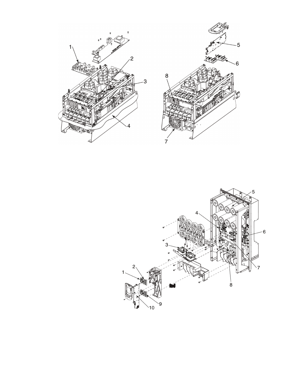
LEGEND
1
— PF750 Series, Precharge Kit
2
— PF750 Series, Gate Interface
3
— PF750 Series, Power Interface
4
— PowerFlex 750 Series, Flange Gasket
5
— PF755 Main Control Board
6
— PF750 Series, Backplane Interface
7
— PF750 Series, Type 4X/12 Chill Plate
(Heatsink) Fan Kit
8
— Chill Plate Fan
NOTE: When replacing the Main Control Board (Item No. 1) the jumper marked
“J1 ENABLE” must be removed and the jumper marked “J1 SAFETY” must be
left in place.
a19-1848
Fig. 27 — Frame 6 Parts
Fig. 28 — Frame 7 Parts
LEGEND
NOTE: When replacing the Main Control Board (Item No. 1) the jumper marked “J1 ENABLE” must be
removed and the jumper marked “J1 SAFETY” must be left in place.
1 — Slot for Gateway (Gateway Not Shown)
2 — PF750 Series, Backplane Interface
3 — PF750 Series, Type 4X/12 Heatsink Fan Kit
4 — PF750 Series, Power Interface
5 — PF750 Series, Bus Cap Assembly
6 — PF750 Series, Power Interface Cable
7 — PF750 Series, Current Transducer Kit
8 — PF750 Series, Precharge Kit
9 — Slot for 24V I/O Module (24V I/O Module Not Shown)
10 — PF755 Main Control Board
a19-1849