Fig. 23 — chill plate fan, frame 6, Fig. 24 — internal fan, frame 6 – Carrier 19XRV User Manual
Page 25
25
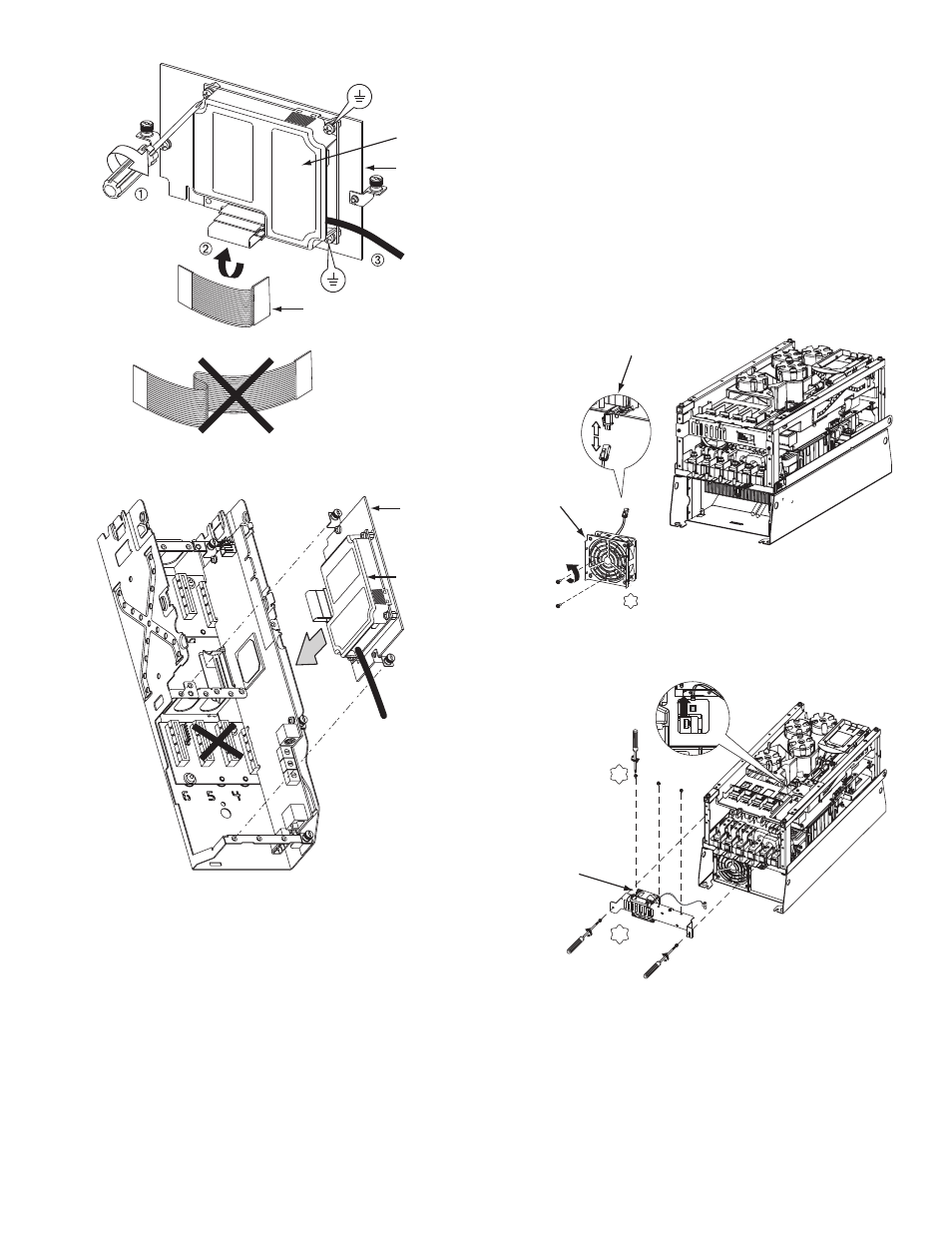
CHILL PLATE FAN AND INTERNAL FAN REPLACE-
MENT — The following are the steps to replace the chill plate
fan and internal fan in Frames 6 and 7.
Frame 6:
1. Disconnect power to the drive. Before removing the en-
closure, open the access door on the front of the drive.
See Fig. 16.
2. Check to be sure that the voltage between DC+ and DC-
and from each DC terminal to the chassis is zero before
proceeding. See Fig. 17.
3. Remove the enclosure. See Fig. 18.
4. Remove and replace the chill plate fan. See Fig. 23.
5. Remove and replace the internal fan. See Fig. 24.
6. Install the enclosure. See Fig. 18.
0.45-0.67 N-m
(4.0-6.0 lb.-in.)
3 PLACES
MOUNTING PLATE
GATEWAY
RIBBON CABLE
Fig. 21 — COMM Card
A19-1819
MOUNTING PLATE
GATEWAY
Fig. 22 — Mount COMM Card Plate to Drive
A19-1820
T20
2.6 N•m (23 lb•in.)
CHILL PLATE
FAN POWER
CONNECTION
CHILL PLATE FAN
Fig. 23 — Chill Plate Fan, Frame 6
A19-1839
T20
2.6 N•m
(23 lb•in.)
T20
2.6 N•m
(23 lb•in.)
INTERNAL FAN
Fig. 24 — Internal Fan, Frame 6
A19-1840
711