IC Realtime H.264E Hybrid DVRs 4/8/16-CH Analog + 4/8/16-CH IP User Manual
Page 31
21
e. When you are connecting two DVRs or you are connecting one DVR and one other
device, please use a relay to separate them,
2. Alarm output
The alarm output port should not be connected to high power load directly (It shall be less
than 1A) to avoid high current which may result in relay damage. Please use the co
contactor to realize the connection between the alarm output port and the load.
3. How to connect PTZ decoder
a. Ensure the decoder has the same grounding with DVR, otherwise you may not control
the PTZ. Shielded twisted wire is recommended and the shielded layer is used to connect
to the grounding.
b. Avoid high voltage. Ensure proper wiring and some thunder protection measures.
c. For too long signal wires, 120Ω should be parallel connected between A, B lines on the
far end to reduce reflection and guarantee the signal quality.
d. “485 A, B” of DVR cannot parallel connect with “485 port” of other device.
e. The voltage between of A,B lines of the decoder should be less than 5v.
4. Please make sure the front-end device has soundly earthed.
Improper grounding may result in chip damage.
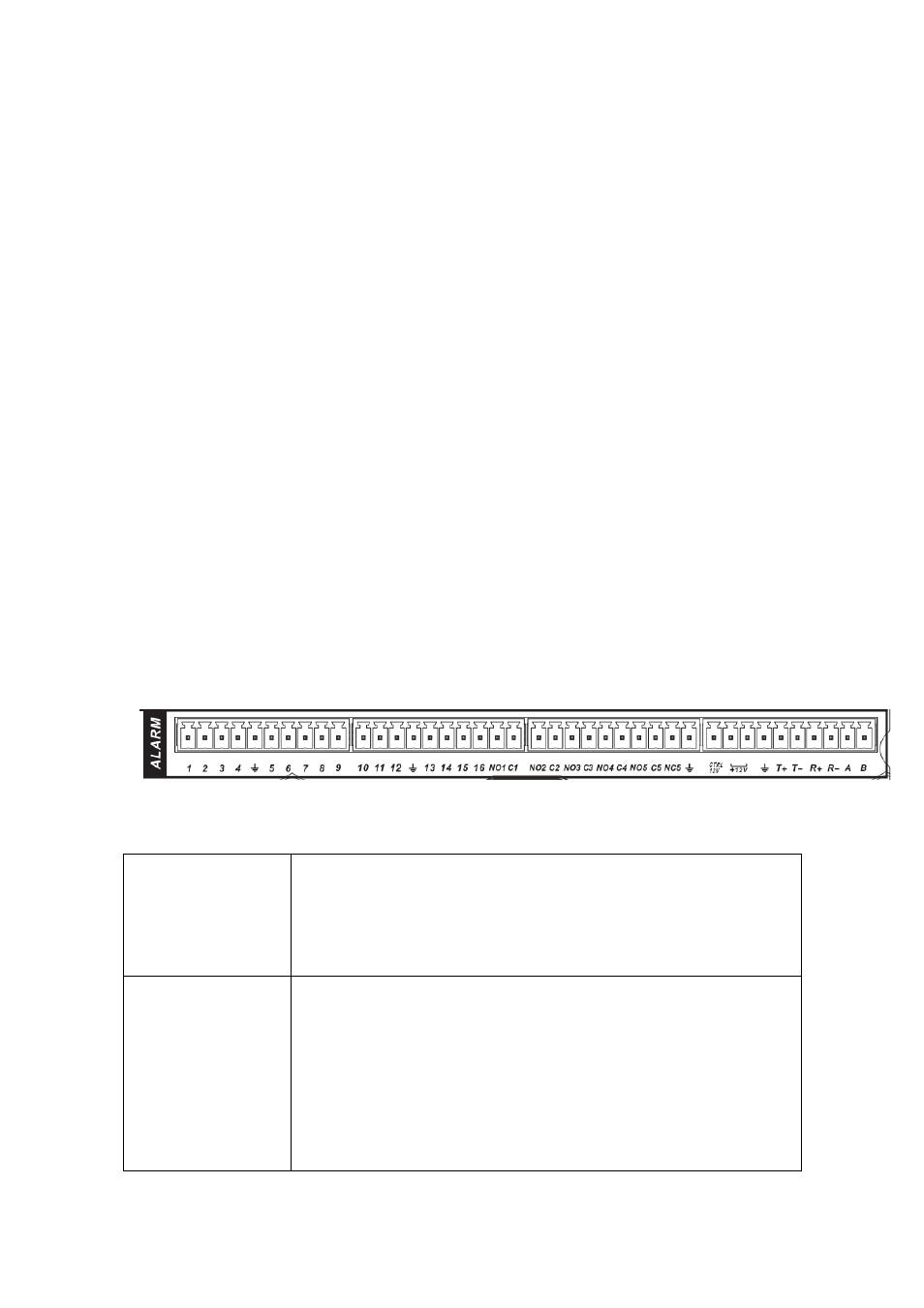
3.8.1 Alarm Input and Output Details
Please refer to the Figure 3-6 and the following sheet for detailed information.
Figure 3-6
In the first line, from
the left to the right,:
1,2,3,4,5,6,
7,8,9,10,11,
12,13,14,15,16
ALARM 1 to ALARM 16. The alarm becomes active in low voltage.
In the second line,
from the left to the
right:
NO1 C1,
NO2 C2,
NO3 C3,
NO4 C4,
NO5 C5 NC5
The first four are four groups of normal open activation output (on/off
button)
NO5 C5 NC5 is a group of NO/NC activation output (on/off button)