Get ready to build – Great Planes Giant Extra 330L Kit - GPMA0250 User Manual
Page 8
(Continued from page 5)
•
Whenever just “epoxy” is specified you may use
either
30-minute epoxy
or 6-minute epoxy. When 30-minute
epoxy is specified it is highly recommended that you
use only 30-minute epoxy because you will need the
working time and/or the additional strength.
•
Where you see the term “glue”, it is at your option to
select the thickness of CA with which you are most
comfortable. If the step indicates a particular thickness of
glue, be sure to use the thickness recommended for
strength, penetration, and/or working time.
•
Several times during construction we refer to the “top” or
“bottom” of the model or a part of the model. For example,
during fuse construction we tell you to “glue the top
stringer”. It is understood that the “top” or “bottom” of the
model is as it would be when the airplane is right-side-up
and will be referred to as the “top” even if the model is
being worked on upside-down. For example, the “top”
stringer is always the “top” stringer even when the fuse is
being built upside-down.
Elev = Elevator
Fuse = Fuselage
LE = Leading Edge (front)
LG = Landing Gear
Ply = Plywood
Stab = Stabilizer
TE = Trailing Edge (rear)
" = Inches
1. Unroll the plan sheets, then reroll the plan inside-out to
make them lie flat.
2. Sort through the sticks and sheets, grouping them by
size. Masking tape can be used to bundle matching sheets
and sticks. Using a felt tip or ballpoint pen, lightly write the
part name or size on each piece or bundle. Refer to the
parts list and plan for sizes and quantities. Use the die-cut
patterns shown on pages 6 & 7 to identify the die-cut parts
and mark them before removing them from the die sheet.
Save all leftovers. If any of the die-cut parts are difficult to
remove, do not force them! Instead, cut around the parts
with a hobby knife or lightly sand the back of the sheet. After
removing the die-cut parts, use your sanding block to lightly
sand the edges to remove any die-cutting irregularities.
3. As you identify and mark the parts, separate them into
groups, such as fuse (fuselage), wing, fin, stab (stabilizer)
and hardware.
DESIGNER’S NOTE: Before you begin construction, it is
important that we take a moment to cover the issues of
structure and weight. This model is designed to be
EXTREMELY lightweight. As such, it is a superb aerobatic
performer and is also VERY structurally sound. However, if
you are concerned about strength and modify the design,
adding material such as sheeting for the bottom of the
fuselage, you may unintentionally increase the flying weight
of the aircraft without adding sufficient structural integrity to
compensate. While one small change won’t likely hurt the
aircraft, small changes quickly accumulate to the point of
actually increasing the risk to the aircraft. If you trust the
design and add nothing, you will be rewarded with an
exceptional flying, extremely durable, gorgeous aircraft.
Because of the incredible light weight of this design, some of
the structure is fragile during construction. Be sure to take
your time and handle the model with care, being particularly
careful about not picking up sheeted areas by the sheeting
for risk of putting your fingers through the sheet, etc. The
balsa cross trusses in the fuse are likewise fragile and
should not be used to pick up the aircraft; however,
structurally they do their job perfectly: in flight, the cross
trusses would never be subject to such a load. Again, do not
let this fragileness concern you, and we strongly
recommend NOT making changes to the design based
upon this apparent fragileness. When completed and
covered, the aircraft is VERY structurally sound.
Zipper-top food storage bags are handy to store the small
parts as you sort, identify and separate them into
sub-assemblies.
GET READY TO BUILD
1/64" = .4mm
1/32" = .8mm
1/16" = 1.6mm
3/32" = 2.4mm
1/8" = 3.2mm
5/32" = 4mm
3/16" = 4.8mm
1/4" = 6.4mm
3/8" = 9.5mm
1/2" = 12.7mm
5/8" = 15.9mm
3/4" = 19mm
1" = 25.4mm
2" = 50.8mm
3" = 76.2mm
6" = 152.4mm
12" = 304.8mm
15" = 381mm
18" = 457.2mm
21" = 533.4mm
24" = 609.6mm
30" = 762mm
36" = 914.4mm
1" = 25.4mm (conversion factor)
Metric Conversions
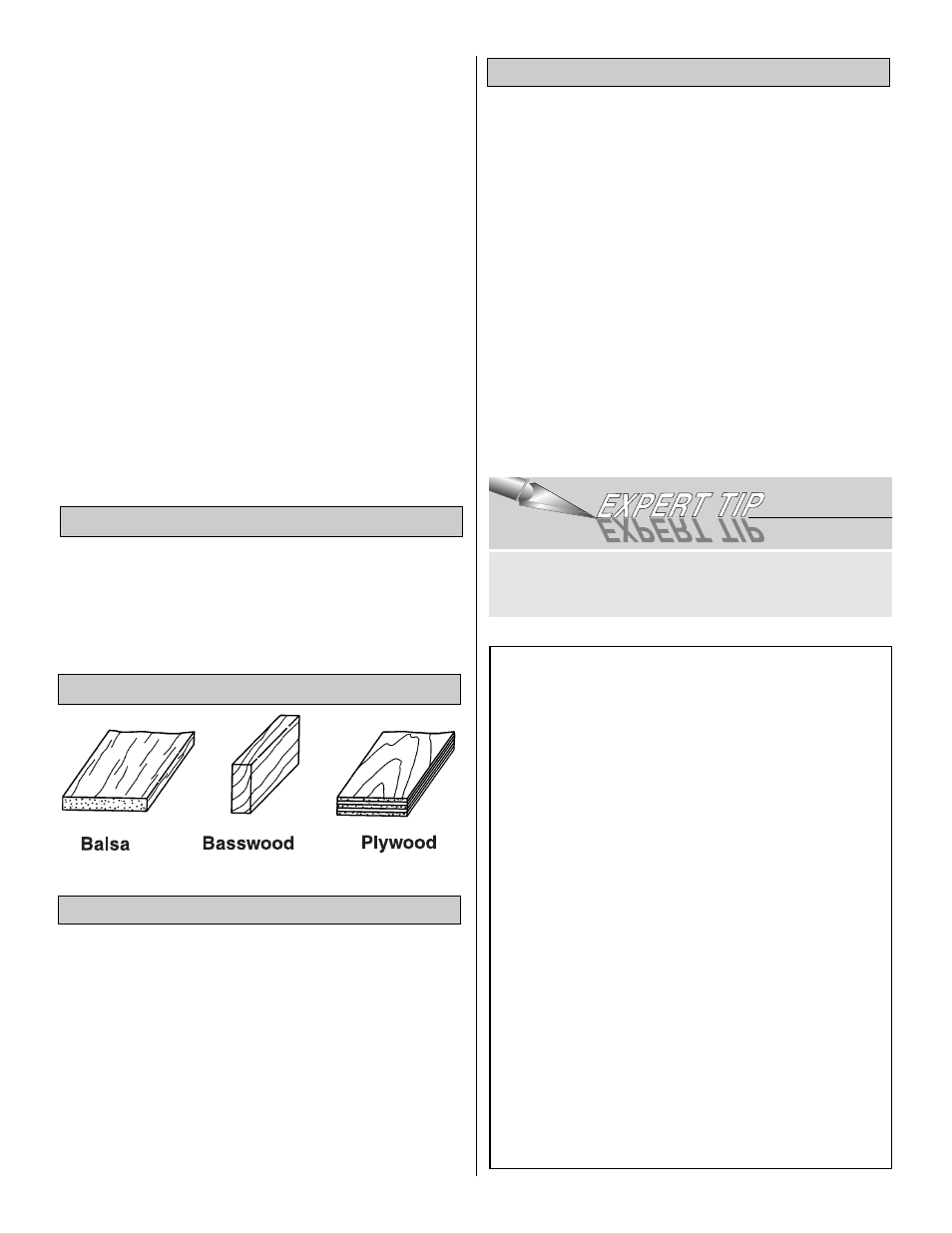
Types of Wood
Common Abbreviations
8