Great Planes Giant Extra 330L Kit - GPMA0250 User Manual
Page 28
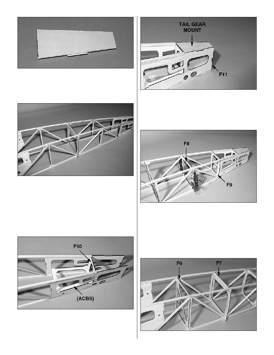
❏ 1. Select the die-cut 1/8" ply tail gear mount (TGM) and
tail gear mount doubler (TGMD). Glue the doubler to the
tail gear mount, aligning the leading and trailing edges. This
assembly is now known as the tail gear mount assembly.
❏ 2. Select the die-cut 1/8" ply former F7. Position your
center box sides inverted over the bottom view plan (the
upper longeron will set flush along the entire length of the
fuse plan.) Temporarily lock F7 in place over the center box
sides in front of the vertical trusses with the “top” label
against your work surface. NOTE: This former is in
position temporarily to help keep the center box sides in
position while you assemble the aft center box. Don't glue
it in place until step 6.
❏ 3. Select the die-cut 1/8" ply aft center box support
(ACBS) and F10. Test fit both pieces between the aft box
sides. When comfortable installing them, glue them in place
with thin CA. Be sure to hold all pieces tightly in place until
your CA has cured completely.
❏ 4. Glue the die-cut 1/8" ply F11 and the tail gear mount
assembly in position. NOTE: The doubler slides in between
the aft box sides with the tail gear mount being flush with
the bottom of the aft box sides.
❏ 5. Position the die-cut 1/8" ply formers F9 and F8 in front
of the vertical trusses, with F8’s top label against the plan.
Glue F9 and F8 in position. HINT: Using C clamps or
regular office clamps to secure the formers to the vertical
trusses while the CA cures will help ensure an excellent
bond.
❏ 6. Position the die-cut 1/8" ply former F6 in front of the
28