Great Planes Corsair 40 Kit - GPMA0177 User Manual
Page 37
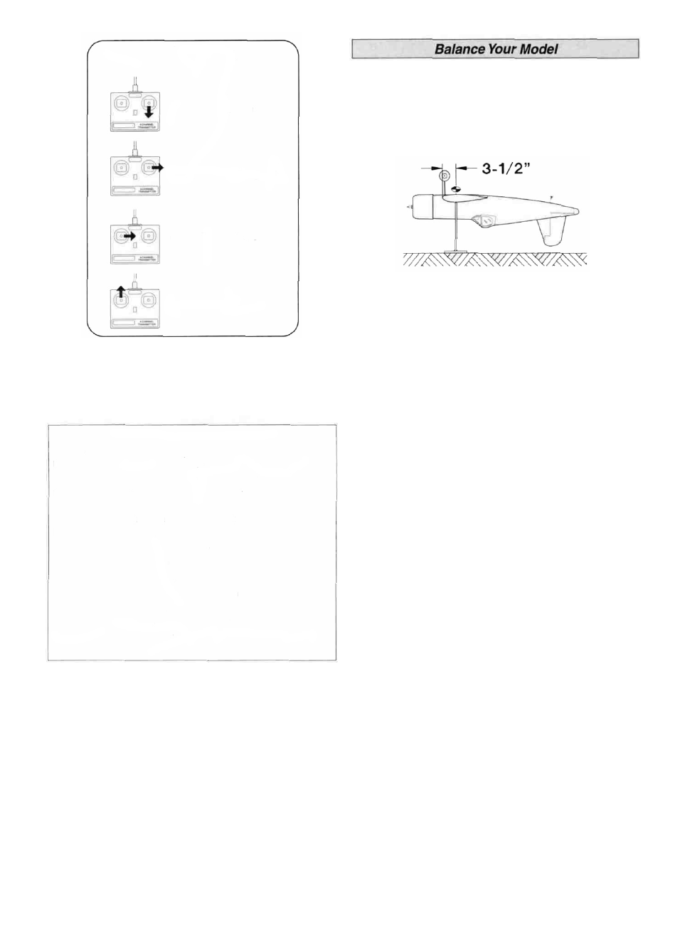
4-CHANNEL RADIO SETUP
(STANDARD MODE 2)
ELEVATOR MOVES UP
RIGHT AILERON MOVES UP
LEFT AILERON MOVES DOWN
RUDDER MOVES RIGHT
CARBURETOR WIDE OPEN
CONTROL SURFACE THROWS
We recommend the following control surface throws:
NOTE: Throws are measured at the widest part of the
elevators, rudder and ailerons Adjust the position of the
pushrods at the control/servo horns to control the amount
of throw.
High Rate Low Rate
ELEVATOR: 1/2" up 5/16" up
5/8" down 3/8" down
RUDDER: 1-3/4" right Same
1-3/4" left Same
AILERONS: 1/4" up 3/16" up
3/8" down 1/4" down
NOTE: If your radio does not have "dual rates," then set
up the control surfaces to move between the high rate
and low rate throws
NOTE The balance and surface throws for this aircraft
have been extensively tested. We are confident that
they represent the settings at which the Corsair 40 flies
best. Please set up your aircraft to the specifications
listed above. If, after a few flights, you would like to
adjust the throws to suit your tastes, that's fine. Too
much throw can force the plane into a stall, so
remember, "more is not better."
NOTE: This section is VERY important and must NOT
be omitted! A model that is not properly balanced will
be unstable and possibly unflyable.
D 1. Accurately mark the balance point on the top of the
wing on both sides of the fuselage The balance point is
shown on the plan (CG), and is located 3-1/2" back from
the leading edge as shown in the sketch and on the plans
Hint: Use the full-size fuse plan to help you accurately
locate the proper balance point This is the balance point at
which your model should balance for your first flights Later,
you may wish to experiment by shifting the balance up to
1/4" forward or back to change the flying characteristics
Moving the balance forward may improve the smoothness
and arrow-like tracking, but it may then require more speed
for takeoff and make it more difficult to slow down for
landing Moving the balance aft makes the model more
agile with a lighter and snappier "feel" and often improves
knife-edge capabilities In any case, please start at the
location we recommend and do not at any time balance
your model outside the recommended range.
D 2 With the wing attached to the fuselage, all parts of the
model installed (ready to fly) and an empty fuel tank, hold
the model upside-down with the stabilizer level.
D 3 Lift the model at the balance point If the tail drops
when you lift, the model is "tail heavy" and you must add
weight* to the nose to balance it. If the nose drops, it is
"nose heavy" and you must add weight* to the tail to
balance it NOTE: Nose weight may be easily installed by
using a "spinner weight" or gluing lead weights into the
engine compartment Tail weight may be added by using
Great Planes (GPMQ4485) "stick-on" lead weights and later
if the balance proves to be OK, you can open the fuse
bottom and glue these in permanently.
* If possible, first attempt to balance the model by changing
the position of the receiver battery and receiver If you are
unable to obtain good balance by doing so, then it w i l l be
necessary to add weight to the nose or tail to achieve the
proper balance point.
37