Great Planes Corsair 40 Kit - GPMA0177 User Manual
Page 20
Note: All fuse formers must be installed with their
die-stamped numbers facing forward. This is to ensure
correct alignment of the pushrod holes and locking tabs.
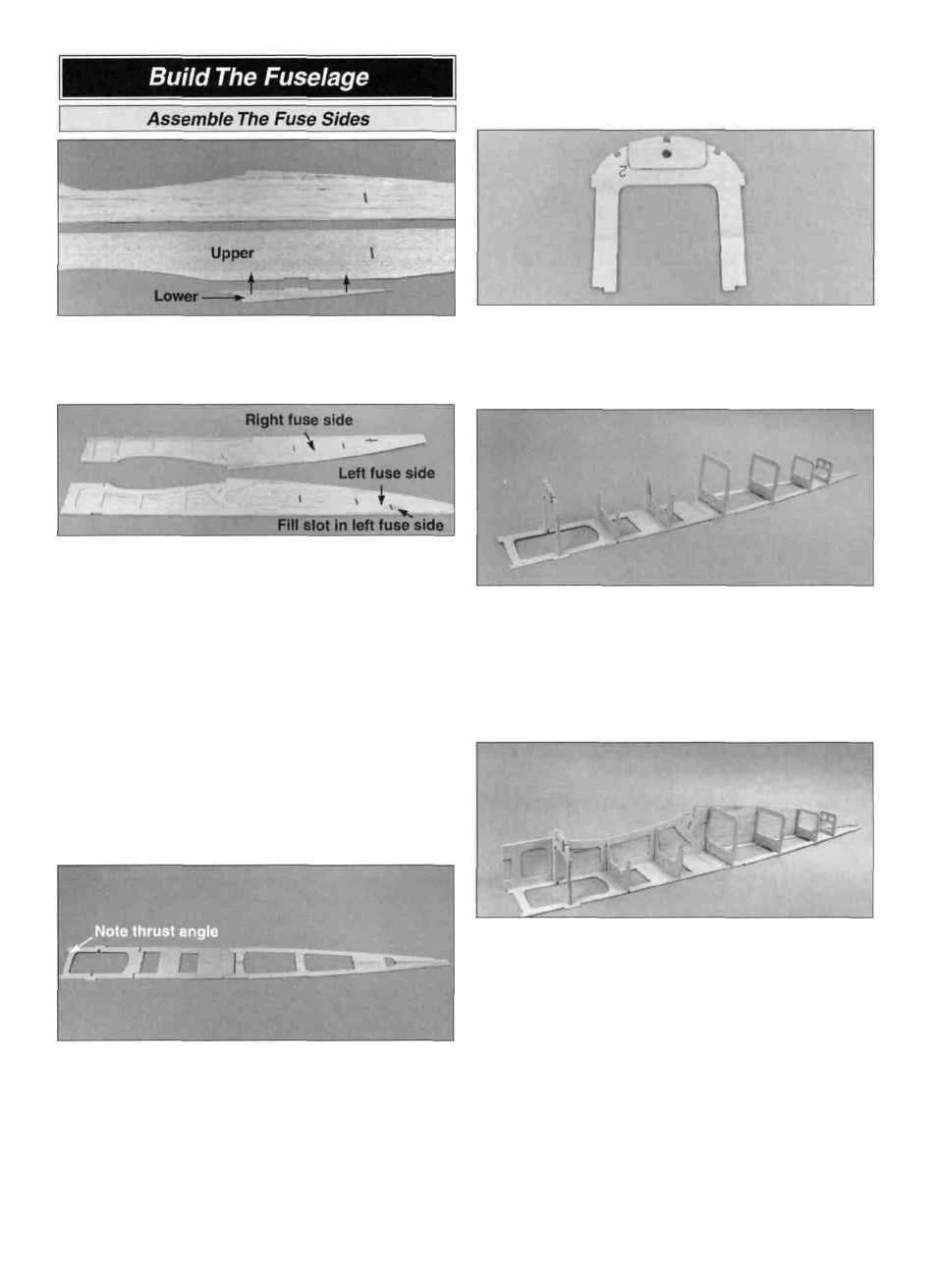
D 1. Locate both die-cut 3/32" balsa upper fuse sides and
lower fuse sides (F05). Glue the upper and lower fuse
sides together with thin CA. Sand the fuse side smooth with
220-grit sandpaper.
D 5. Use 6-minute epoxy to glue the 1/8" die-cut ply
doubler C-2 (F02) to the front of the 1/8" die-cut ply former
F-2 (F02). The hole through C-2 must be aligned with the
hole through former F-2.
D 2. Place the fuse sides on a flat work surface with the
wing saddles facing each other as shown in the photo. Use
medium CA to glue the die-cut 1/8" ply fuse doublers
(F01) in position. The edges must be flush, and the 1/8" x
1" notch at the forward end of each fuse side must exactly
match the doublers' notch. Note: Make a right and a left
fuse side. The right side has a slot for the outer pushrod
tube exit. Use the pieces from the die-cutting to fill in the
pushrod exit slot in the left fuse side.
Note: The formers are stamped only with the necessary
part of their names.
Note: The fuse is built upside-down over the plans. The
plan sheet may be cut apart if space is a problem.
D 3. Cover the bottom view of the fuselage plans with
waxed paper.
D 6. Draw a centerline on the side of F-9 (F02) opposite the
stamped part name. Drill a 3/16" hole at at each punch
mark on formers F-4, F-6, F-7 and F-8. Glue F-2, F-3, F-4,
F-6, F-7, F-8 and F-9 (F03) into the notches of the forward
crutch and the aft fuse top as shown. Use a triangle to hold
all the formers vertical while the CA cures. Make sure the
embossed labels on the formers face forward.
D 7. Fit a fuse side in position. Make sure all of the tabs
are fully seated in the notches. Wick thin CA into all joints
between the formers, the forward crutch and the aft fuse
top. Add a fillet of medium CA to one side of each former
where they touch the fuse sides. Repeat this operation for
the other fuse side.
D 4. Position the two 1/8" die-cut balsa aft fuse top halves
(FO6) and the 1/8" die-cut ply forward crutch (F04) over
the plans. Glue the two aft fuse top halves together with thin
CA. Then, glue the aft fuse top and forward crutch together.
Warning: When aligning the forward crutch over the plans,
make sure the proper thrust angle is set at the front.
D 8. Glue the 1/8" die-cut ply former F-10 (F02) between
the fuse sides, flush with the aft edge of the fuse. Use a
triangle between the fuse side and the building board to
check vertical alignment of F-10.
20