Great Planes Corsair 40 Kit - GPMA0177 User Manual
Page 21
D 9. Glue the 1/8" die-cut ply former F-5 (F03) into the
notches of the fuse doubler.
D 3. Trim and sand the outer pushrod tube that protrudes
from the fuse, flush with the fuse side.
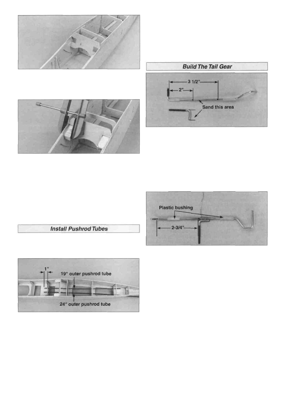
D 1. Using 220-grit sandpaper, sand the area 2" to
3-1/2" from the top of the tail gear wire (WBNT233) and
the unthreaded end of the tail gear arm (WBNT234).
Wipe the wires clean with rubbing alcohol.
D 10. Use 30-minute epoxy to glue the 1/2" x 3/4" x 1-3/8"
hardwood wing bolt blocks (F12) into the notches at F-5.
Add fillets of epoxy all around these blocks, for a secure bond.
D 11. Remove the lower fuse frame from the building board
and give it a quick once-over with a sanding block and 150-
grit sandpaper.
D 1. From the two remaining 24" long outer pushrod
tubes (PLTB011), cut one 19" long. Sand the outside of
both tubes with 80-grit sandpaper to roughen them.
D D 1. Place a mark 2-3/4" from the top of the tail gear wire.
Using the 8" piece of wrapping wire (WIREF14), attach the
tail gear arm to the tail gear wire so that the threaded
portion of the tail gear arm is aligned with the mark and
parallel to the tail wheel shaft. Note: Make sure that one
plastic bushing is above the tail gear arm and one is below.
D 2. Slide the 19" outer pushrod tube through the holes in
the left side (as viewed from the tip of the fuse) of formers
F-4, F-6, F-7 and F-8. Slide the 24" tube through the holes
on the right side and out the slot in the fuse side. About 1"
of the tubes should protrude forward of F-4. Glue the
pushrod tubes to all of the formers and to the inside of the
fuse sides with medium CA.
D 3. Apply soldering flux to the wrapped area. Using a hot
soldering iron, solder the tail gear arm to the tail gear wire.
Be careful not to melt the plastic bushings. After the tail
gear wire has cooled, trim off the excess wrapping wire.
Clean the area with rubbing alcohol to remove any flux.
21