Great Planes Corsair 40 Kit - GPMA0177 User Manual
Page 23
D 2. Test fit the firewall in the fuse. Remove any cured epoxy
that may prevent the firewall from seating tight against the
fuse sides and fuse doubler. The firewall angles slightly to
the right to compensate for torque. The left side of the
firewall is flush with the front of the fuse side. There is a
slight gap between the firewall and the fuse doubler. Cut
three pieces from the 1/2" x 12" triangle stick (F08) to fit
between the firewall, fuse sides and forward crutch. After you
are satisfied with the fit, epoxy the firewall and triangle sticks
to the fuse with 30-minute epoxy.
D 3. After the epoxy has cured, sand the fuse sides flush
with the front of the firewall..
D 4. From a 3/16" x 3/16" x 30" balsa stringer (F07), cut and
glue a stringer into each notch from the firewall to former F-2.
Sand the stringers flush with the firewall and former F-2.
With the sheet pressed against the firewall and former F-2
use medium CA to glue one piece to the right fuse side
only. The joint between the fuse side and the sheeting will
be slightly offset.
D 6. Wet the outside of the sheet with water and let it soak
in for a few minutes. Firmly, yet carefully, pull the sheet
around the firewall and mark where it crosses the centerline
of the 3/16" square center stringer. Cut the sheet on the line
you marked.
D 7. Pull the sheet into position and glue it in place.
D 8. Apply the sheet to the other side in the same manner
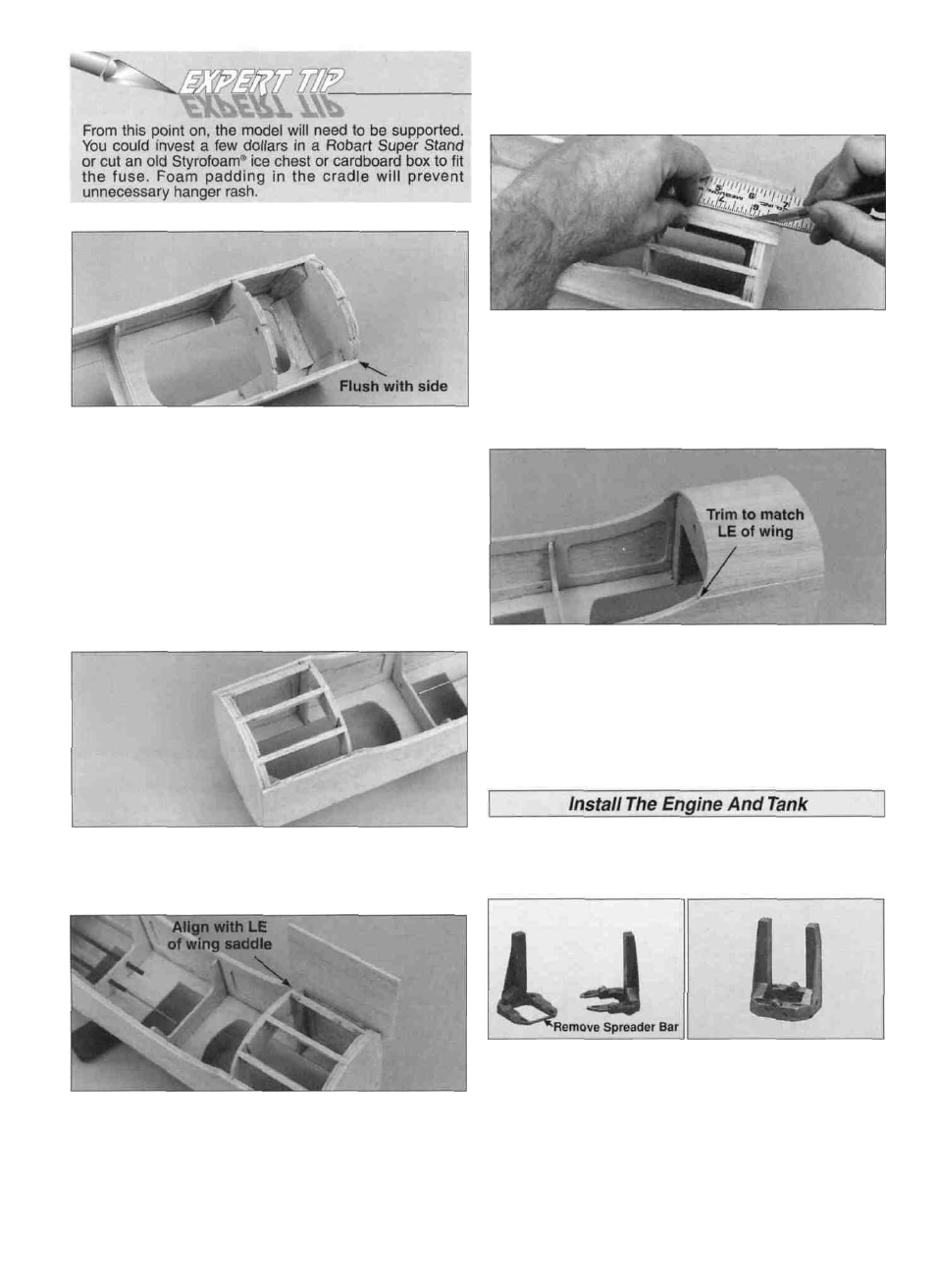
as described above. Sand the sheeting flush with the
firewall and trim it to match the LE of the wing at the
wing saddle.
The Great Planes adjustable engine mount is simple and
convenient to use. It may be used to mount most .40 - .60
two-stroke and .40 - .70 four-stroke engines.
D 5. Cut Two 4" long pieces from the 3/32" x 3" x 8-7/8"
balsa front lower sheet (F17). Fit the lower sheet so that
the rear corner is aligned with the LE of the wing saddle.
D 1. Cut or break the "spreader bar" from each mount half.
Carefully trim any extra material left by the spreader bar
from each mount half. The surface where the spreader bars
were attached must be smooth to allow the mount halves to
fit together. Trim the flashing off any rough edges if
necessary. Assemble the mount halves as shown.
23