Great Planes Corsair 40 Kit - GPMA0177 User Manual
Page 34
We have found that it's much simpler to do all hinging and
control horn installation after the model is covered.
D 1. Cut the hinge slots in the stab and elevators using the
technique described in the Expert Tip section following
these four steps Test fit the elevators to the stab with the
joiner wire in position When satisfied with the fit, remove
the elevators Pack the joiner wire holes in the elevators
with 30-minute epoxy Then install the elevators on the stab
Make sure that both elevators are parallel with each other
Use a paper towel dampened with rubbing alcohol to
remove any excess epoxy that squeezes out.
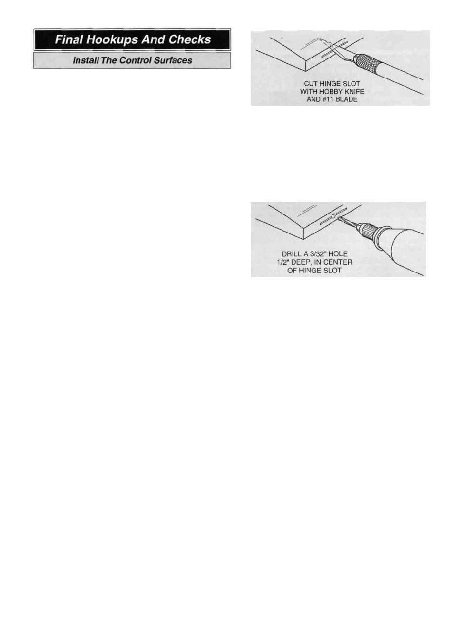
D 1. Cut the hinge slot using a #11 blade in a standard #1
knife handle The CA hinges provided have a thickness
that fits this type of slot very well Trial fit the hinge into
the slot. If the hinge does not slide in easily, work the
knife blade back and forth in the slot a few times to
provide more clearance (it is really the back edge of the
blade that does the work here in widening the slot).
D 2 Install the rudder following the same procedure used
to install the elevators
D 3. Install the ailerons on the wing, using four hinges
each.
D 4 After the epoxy has cured, CA the hinges in the control
surfaces.
Note: Refer to the fuse plan for the hinge making
instructions. Cut 16 hinges from the 2" x 9" supplied
material
D Drill a 3/32" hole, 1/2" deep, in the center of the
hinge slot. If you use a Dremel Moto-Tool for this task, it
will result in a cleaner hole than if you use a slower
speed power or hand drill Drilling the hole will twist some
of the wood fibers into the slot, making it difficult to insert
the hinge, so you should reinsert the knife blade, working
it back and forth a few times to clean out the slot.
C. Trial fit the hinges into the slots and temporarily attach
the control surface to verify the fit and operation
The hinge material supplied in this kit consists of
a 3-layer lamination of mylar and polyester It is specially
made for the purpose of hinging model airplane control
surfaces Properly installed, this type of hinge provides
the best combination of strength, durability and ease of
installation We trust even our best show models to these
hinges, but it is essential to install them correctly.
Please read the following instructions and follow them
carefully to obtain the best results These instructions
may be used to effectively install any of the various
brands of CA hinges.
The most common mistake made by modelers when
installing this type of hinge is not applying a sufficient
amount of glue to fully secure the hinge over its entire
surface area, or, the hinge slots are very tight, restricting
the flow of CA to the back of the hinges This results in
hinges that are only "tack glued" approximately 1/8" to
1/4" into the hinge slots The following technique has
been developed to help ensure thorough and
secure gluing.
D Rather than just making a single slit, it is better to cut
away a narrow rectangle of covering to provide an
adequate opening for the CA glue to wick into the slot.
E Insert the hinges and install the control surface Verify
the left-right positioning of the control surface, and close
up the hinge gap to 1/32" or less It is best to leave a very
slight hinge gap, rather than closing it up tight, to help
prevent the CA from wicking along the hinge line Make
sure the control surface will deflect to the recommended
throws without binding If you have cut your hinge slots
too deep, the hinges may slide in too far, leaving only a
small portion of the hinge in the control surface To avoid
this, you may insert a small pin through the center of
each hinge, before installing This pin will keep the hinge
centered while installing the control surface Remove the
pins before proceeding
34