Great Planes Corsair 40 Kit - GPMA0177 User Manual
Page 18
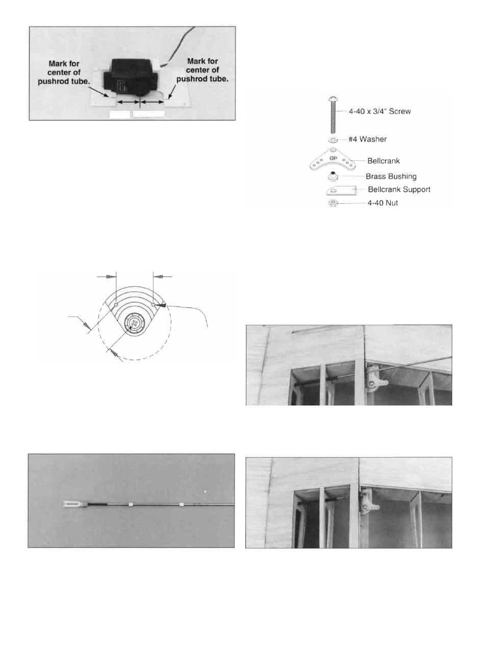
Equal distance
D 3. Position the 1/16" die-cut birch ply aileron servo
hatch (W01) over the aileron servo bay and mark the
location of the outer pushrod tubes. Position the aileron
servo on the hatch positioned so that the servo wheel is
centered in the opening of the hatch and aligned with the
marks for the outer pushrod tubes. Use 30-minute epoxy to
glue two 5/16" x 3/4" x 7/8" basswood servo mount blocks
(P516W28) to the aileron servo hatch.
onto each pushrod, spacing them about 2" apart starting 2"
from the threaded end. If the bushings are too loose, put a
drop of thin CA on the pushrod at each bushing.
D 8. Attach the clevises to the aileron servo wheel. Insert
the pushrod in the outer pushrod tube located in the aileron
servo bay.
D 4. When the epoxy has fully cured, fit a 1/32" to 1/16"
temporary shim between the servo and the plywood hatch.
Drill 1/16" pilot holes and mount the servo to the blocks.
Then remove the shims.
1/2"
1/16" HOLE
D 5. Trim a servo wheel as shown. Then install it on
the servo.
LI 6. Position the aileron servo hatch on the servo bay. Drill
1/16" pilot holes through the hatch and hatch blocks at the
embossed marks on the hatch. Remove the hatch and place
a drop of thin CA in each hole in the hatch blocks. Wipe off
the excess CA and reinstall the hatch. Secure the hatch to
the wing with five #2 x 3/8" sheet metal screws (SCRW024).
D 9. Locate the 1/8" die-cut ply bellcrank supports (F01).
Assemble the bellcrank parts on the supports as shown
above making a left and a right. Put a drop of medium CA
on the nut and the threads of the 4-40 bolt to prevent the
nut from vibrating loose.
D 10. Align the outermost hole in the bellcrank with the
pushrod. Use medium CA to glue the bellcrank support to
rib T-1 and the shear web. Then, apply a fillet of thick CA
along the joint.
3 / 4 "
D 7. Thread two nylon clevises (NYLON17) thirteen
complete turns onto two 2-56 x 1 2 " threaded rods
(WIRES16). Slide silicone clevis retainers (PLTB021)
over the clevises. Cut four 3/16" long bushings from the
6-1/2" inner pushrod tube (PLTB004). Slide two bushings
D 11. Attach a solder clevis (METAL030) to the outermost
hole in the bellcrank. Align the bellcrank so that it is
perpendicular to the pushrod. Cut the pushrod and solder
the clevis on the end of it. Silver solder is highly
recommended. Reinstall the control rod on the bellcrank.
18