Great Planes Corsair 40 Kit - GPMA0177 User Manual
Page 24
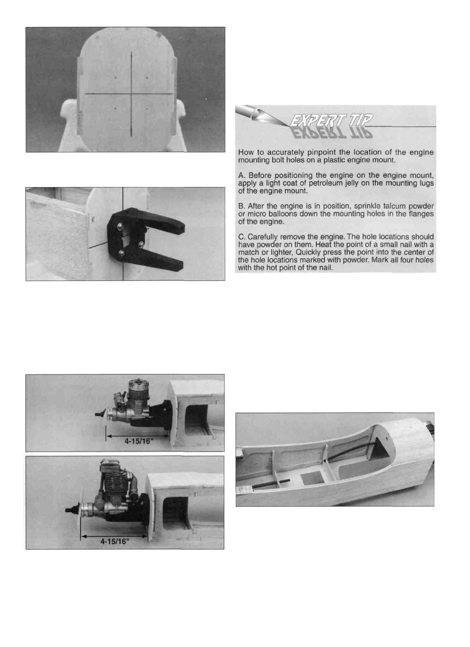
D 2. Draw a centerline on F-1A by connecting the punch
marks on the firewall.
marks on the mount. Tighten the 6-32 screws to hold the
mount firmly in position against the firewall. Position the
engine so that the front of the drive washer will be 4-15/16"
in front of the firewall. Mark the engine mounting holes on
the mount. Remove the engine and drill a 7/64" hole
through the beams at each mark. Install the engine with the
6-32 x 3/4" sheet metal screws (SCRW018) that have
been provided with this kit.
D 3. Drill a 11/64" diameter hole at each of the four die-
punch marks on F-1A. Then install the mount sideways
using four 6-32 x 1" machine screws (SCRW008), #6 flat
washers (WSHR004) and 6-32 blind nuts (NUTS003).
Tighten the machine screws all the way to draw the blind
nuts into position, then loosen them slightly to allow the
mount to be adjusted to fit the engine. Secure the blind nuts
to the firewall with a drop or two of medium CA around the
flange.
Note: When installing an O.S. .70 4-stroke engine, you will
need to remove the choke mechanism in order to position
the engine far enough back on the mounting rails to achieve
the 4-15/16" distance from the firewall.
D 4. Slide the engine mount halves apart until the engine
mounting lugs will sit flat on the beams. Adjust the mount
until the firewall centerline is centered between the "tick"
D 5. Mark the location for the throttle pushrod hole on F-1A.
DI 6. Use a 3/16" drill bit to drill a hole through the firewall at
the throttle hole location you marked in step 5. Cut and
insert an 8" length of remaining outer pushrod tube
through the firewall. Mark formers F-2 and F-3 where the
tube needs to pass through. Drill a 3/16" hole through the
formers or cut notches at the marks. Adjust the outer
pushrod tube so that it extends 1/4" past the firewall. Glue
the tube in place.
24