Great Planes Corsair 40 Kit - GPMA0177 User Manual
Page 25
D 7. Cut off approximately 1/2" of threads on the 4"
threaded rod (WIRES72). Completely screw the threaded
rod into one end of the 12" inner pushrod tube
(PLTB012). Attach a solder clevis to the throttle arm and
insert the inner pushrod tube into the outer pushrod tube in
the firewall. With 3/4" of inner pushrod tube protruding from
the outer pushrod tube, bend the threaded rod to clear the
muffler. Rotate the throttle arm toward the firewall and mark
the location where the threaded rod passes through the
solder clevis. Cut the threaded rod at the mark and solder
the clevis onto it.
We strongly recommend that the engine be removed from
the engine mount and stored back in its box to prevent dust
from entering the engine.
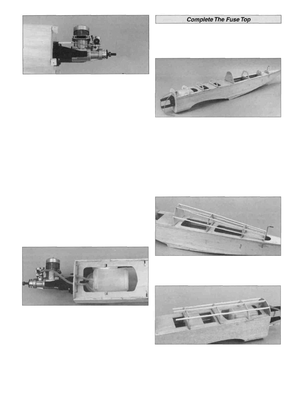
D 1. Glue the die-cut ply formers F-2B, F-3B, F-4B, F-6B,
F-7B, F-8B and F-9B (F02, F03 and F04) into their notches
on the fuse top. Use a triangle to maintain the vertical
alignment of the formers.
D 2. From a piece of 1/8" scrap ply, cut two 1/2" x 3-1/2"
servo tray doublers. Glue the doublers on the forward and
aft edges of the servo cutout in the forward crutch.
Note: We used a 10 oz. Great Planes Tank (#GPMQ4104)
in out prototypes. By using the supplied right angle fuel
supply tube, the fuel tubing can be routed to the top of the
firewall without the risk of kinking the tube. You may also
route the fuel tube below the forward crutch to make fishing
the tubes a little easier. The choice is yours.
D 8. Temporarily install the fuel tank. It's much easier to see
what is happening at this stage of construction. Decide
where you want the fuel and vent tubes to exit the firewall
and mark the locations. Remove the tank and drill two
15/64" (or 7/32") fuel tube exit holes through the firewall at
the locations you marked. Before reinstalling the fuel tank,
fuelproof the fuel tank compartment. Wrap the fuel tank in
foam to prevent fuel foaming from vibration. Reinstall the
tank and connect the fuel tubes. Check for kinks and rectify
any problems before proceeding.
D 3. Cut two of the 3/16" x 3/16" x 30" balsa stringers in
half. Fit the stringers from former F-6B to F-9B and glue
them in place with thin CA. Sand the end of the stringers
flush with F-6B and F-9B.
D 4. Cut three 13" long pieces f r o m the remaining
3/16" x 3/16" balsa. Install the stringers flush with the front
of the firewall, allowing them to overhang former F-4B.
25