Great Planes Corsair 40 Kit - GPMA0177 User Manual
Page 35
ASSEMBLE, THEN APPLY 6 DROPS
OF THIN CA TO CENTER
OF HINGE, ON BOTH SIDES
F. Apply 6 drops of thin CA adhesive to both sides
of each hinge, allowing a few seconds between drops
for the CA to wick into the slot. Note that the small
"tunnels" you created by drilling the 3/32" holes allow the
CA to freely travel in to the entire surface of the hinge,
producing an extremely secure bond.
THE CA WICKS ALONG THE
•TUNNELS" TO THE ENTIRE
HINGE SURFACE
D 1. Secure the tail wheel to the tail gear with two 3/32"
wheel collars.
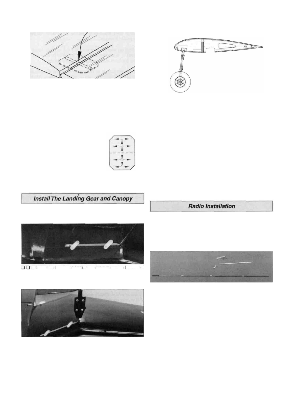
D D 2. Seat the landing gear in the groove on the bottom of
the wing. Secure it with two nylon straps (NYLON36) and
four #2 x 3/8" sheet metal screws per gear.
strap. Attach the gear door to the hump strap with two
#4 x 3/8" sheet metal screws (SCRW043) inserted from the
front of the door into the strap. Repeat the process for the
other hump strap.
D 4. The landing gear should be positioned as shown in the
sketch above, with the wheel under the L.E.
D 5. Paint the inside of the cockpit light gray (your option).
Trim and install the instrument panel decal.
D 6. Position the canopy on the fuse as shown on the
plans, then lightly trace its edges on the covering with a
ballpoint pen. Trim about a 1/16" wide strip of covering from
around the line you just traced. By removing covering the
canopy will adhere better.
D 7. Before installing the canopy you may wish to add a pilot
figure. We added a block of balsa to the bottom of a
2-1/2" Williams Bros. Pilot to give the pilot the proper height.
D 8. Clean the inside of the canopy with window cleaner
and allow it to dry. Use R/C-56* or 6-minute epoxy to glue
the canopy in position.
Note: You should wrap a flat battery pack with 1/4" foam
rubber (HCAQ1000) and install the battery under the
fuel tank.
D 1. Mount three servos in the servo tray following the
manufacturer's recommendations. Install "cross" style horns
on all servos, cutting off the unused arms.
D D 3. Center the landing gear doors on the landing gear.
Hold a nylon hump strap (NYLON30) on the back of the
gear door and mark the location of the holes in the hump
D 2. Slide a silicone retainer over the "hex" end of a nylon
clevis. Screw the clevis 14 turns onto the threaded end of a
36" wire pushrod. Cut the unthreaded end to shorten the
wire to 28". Cut five 3/16" bushings from the plastic inner
pushrod tube provided in the kit. Slide the bushings on the
wire pushrod, spacing them about 3" apart as shown on the
plans. If they are too loose, put a drop of thin CA on the
pushrod wire at each bushing to hold them in place. Locate
the two bushings on both ends so that they will not exit
the pushrod tubes. Trim the backing plate from a nylon
control horn, then clip the clevis to the outer hole of the
horn. Make a second pushrod assembly exactly the same
as the first.
35