GME G142CFD User Manual
Page 40
G - C O M B O
I N S T R U C T I O N M A N UA L
PA G E 4 1
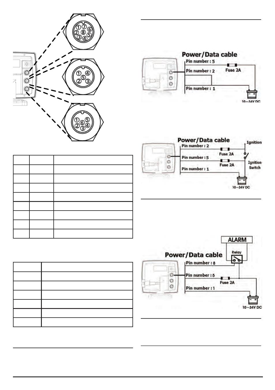
[Power & Data(ALARM, Auto power)]
NO. Color
Function
1
Black
Ground: - power in, NMEA ground.
2
Brown
Ignition_On
3
White
NMEA 1 Out
4
Blue
NMEA 1 In
5
Red
+ power in, 12 to 34 V DC
6
Orange
NMEA 2 Out
7
Yellow
NMEA 2 In
8
Green
External alarm
[Sonar]
Pin NO.
Detail
1
SONAR +
2
SPEED / TEMP. GND
3
SPEED / + SUPPLY
4
TEMP.
5
SONAR -
6
SONAR GND
5-2 Connections
The GPS chart plotter has connectors that are used to connect
to the power supply, GPS antenna and to NMEA devices such
as VHF’s AIS receivers, digital instruments and autopilots.
5-3 Power/data cable
Basic power
• Wire the display unit for basic power as picture below.
Auto power
• Wire the display unit for auto power as picture below.
• During setup, set up Auto power off.
5-4 Alarm
• Wire the chartplotter for any external alarm beepers or
lights as below picture.
• The output from the unit to the external alarm is maximum
30 V DC 200 mA. It is needed to fit a suitable relay.
5-5 GPS antenna
Selecting an antenna:
Fit one of these GPS antennas:
5-5-1 Internal antenna
The chartplotter is supplied with an internal GPS antenna, you
can use it without the input of an external signal.