System no. w-l-7145 – FloAire Pyroscat Enclosure User Manual
Page 56
www.morganthermalceramics.com
Page 55
P029_02:2014
Fire Rated Enclosure
Installation Technique and Design
Advisory Manual
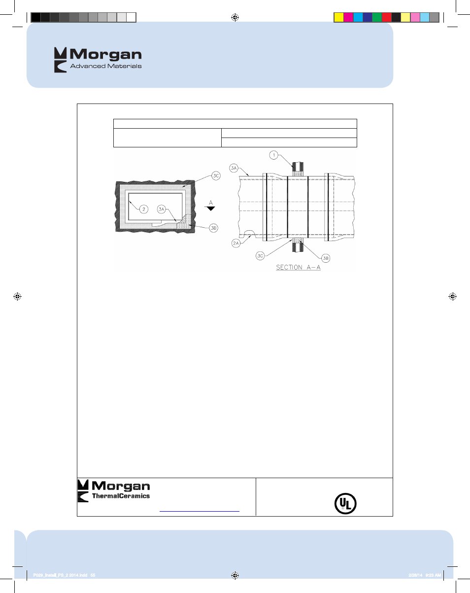
System No. W-L-7145
2102 Old Savannah Road, Augusta, GA Reproduced Courtesy of Underwriters Laboratories Inc.
www.morganthermalceramics.com Created or Modified July 20, 2011
Technical Support:
(706) 796-4306
W-L-7145
Page 1 of 2
ANSI/UL1479 (ASTM E814)
L Rating At Ambient - Less Than 1 CFM/sq ft
F- and T- Rating – 1 and 2 Hr (See Item 1)
L Rating At 400 F - Less Than 1 CFM/sq ft
1. Wall Assembly — The 1 or 2 hr fire-rated gypsum board/stud wall assembly shall be constructed of the materials and in
the manner specified in the individual U400 or V400 Series Wall and Partition Design in the Fire Resistance Directory
and shall include the following construction features:
A. Studs — Wall framing shall consist of min 3-1/2 in. (89 mm) wide channel shaped steel studs spaced max 24 in. (610
mm) OC. Additional framing members shall be installed in stud cavity to form a rectangular box around the penetrant.
B. Gypsum Board* — 5/8 in. (16 mm) thick with square or tapered edges. The gypsum board type, thickness, number
of layers, fastener type and sheet orientation shall be as specified in the individual U400 or V400 Wall and Partition
Design. Max area of opening is 78 ft.2 (7.3 m
2
) with a max dimension of 107 in. (272 cm).
The hourly F and T Ratings of the firestop system are equal to the hourly fire rating of the wall assembly in which
it is installed.
2. Steel Air Duct — One steel duct to be installed within the firestop system. Duct to be rigidly supported on both sides of
wall assembly. Min 26 gauge (0.5 mm) galv steel duct having a max perimeter dimension of 400 in. (0.274 m) and a max
individual dimension of 100 in. (762 mm).
3. Firestop System — The firestop system shall consist of the following:
A. Duct Wrap Materials* — Nom 1-1/2 in. (38 mm) thick blanket totally encapsulated within foil-scrim facers. The
steel air duct shall be wrapped with one layer of duct wrap installed in accordance with Ventilation Assembly Nos. V-
1 or V-19. See Ventilation Duct Assemblies in Vol. 2 of the Fire Resistance Directory. When steel angles (Item 3D)
are used, the edges of the duct wrap material are to about the protruding leg of the angle and the tight seam is to be
covered with an additional 6 in. (152 mm) wide "collar" of duct wrap. The annular space between the insulated duct
and the periphery of the opening shall be min 0 in. (0 mm, point contact) to max 2 in. (51 mm).
THERMAL CERAMICS INC — FireMaster FastWrap XL and FastWrap+ or Pyroscat Duct Wrap XL
B. Packing Material — Min 3-1/2 in. (89 mm) and 4-3/4 in. (121 mm) thickness of unfaced scrap duct wrap material or
min 4 pcf (64 kg/m
3
) mineral wool batt insulation firmly packed into the opening as a permanent form for 1 and 2 hr
rated walls, respectively. Packing material to be recessed from both surfaces of wall as required to accommodate the
required thickness of fill material (Item 4B).
C. Fill, Void or Cavity Material*— Sealant — Min 5/8 in. (16 mm) thickness of fill material applied within annulus,
flush with both surfaces of wall assembly. A min 1/4 in. (6 mm) diam bead of sealant shall be applied at the gypsum
board/insulated duct interface on both surfaces of wall assembly.
SPECIFIED TECHNOLOGIES INC — SpecSeal 100, LC150, LCI Sealant, or Pensil 300 Silicone Sealant
P029_Install_PS_2 2014.indd 55
2/28/14 9:23 AM