FloAire Modular DX System User Manual
Modular dx system installation instructions, Warning, Refrigerant piping practices
Modular DX System
Installation Instructions
WARNING
•
Installing, start-up, and servicing air-conditioning
equipment can be dangerous due to system pressures,
electrical components, and equipment locations.
•
Only trained, qualified installers and service technicians
should install, start-up, and service this equipment.
•
Untrained personal can perform basic maintenance
functions such as cleaning coils. All other operations
should be performed by trained service personnel.
•
When working on the equipment, observe precautions
in the literature and on decals, labels, and tags attached
to the equipment.
•
Follow all safety codes. Wear safety glasses and work
gloves. Keep quenching cloth and fire extinguisher
nearby when braising.
•
Use safe lifting practices when lifting and setting
equipment.
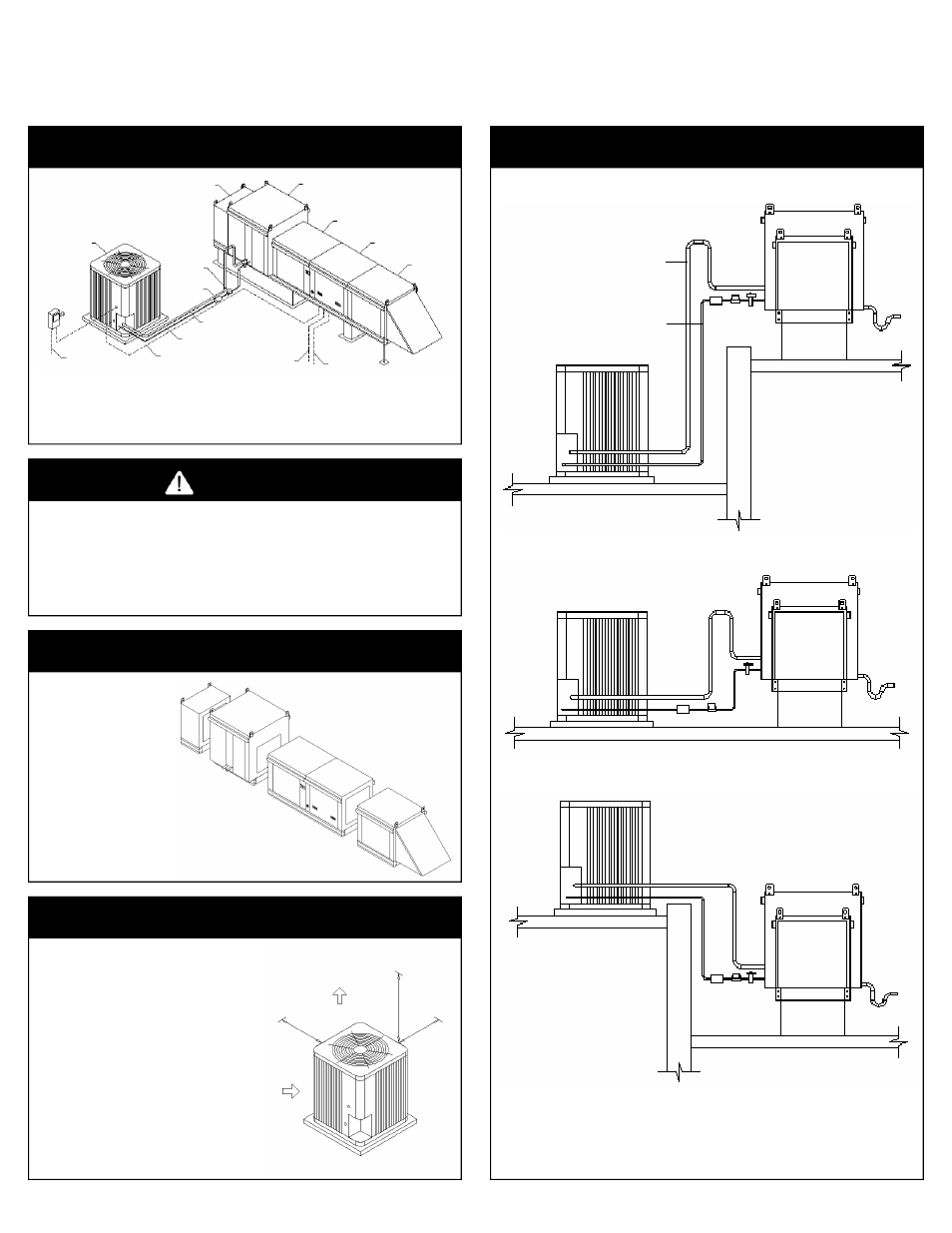
REFRIGERANT PIPING PRACTICES
Typical Piping When Condenser Is Below The AMU
Typical Piping On Same Level
Typical Piping When AMU Is Below Condenser
Notes:
1. Maximum refrigerant line length 100 feet.
2. Do not bury refrigerant lines underground.
3. Accumulators are required on refrigerant line lengths of 75 to 100 feet.
4. Maximum refrigerant liquid lift 60 feet.
5. Dual circuit systems require two suction and liquid lines.
INSPECT UNIT
•
Inspect unit for damage.
•
Look for damage done to the
casing, coils, or ship loose
components.
•
Contact factory service depart-
ment if damage is found on the
unit.
•
Verify that the power and gas
supply to the unit matches the
unit nameplate ratings.
•
Call the factory service depart-
ment with any installation
questions.
TYPICAL PIPING AND WIRING
Notes:
1.
Read the equipments “Installation and Operation Guide” before installing this equipment.
2.
All Piping must follow standard refrigerant piping techniques.
3.
All wiring must comply with all local and national codes.
4.
Call the factory service department with any installation questions.
Condensing
Unit
Field Wired
Power Supply
Weatherproof
Fused
Disconnect
Per NEC
Field Wired
Control Wires
Liquid Line
Suction Line
Filter Drier
Sight Glass
Downturn
Plenum
DX Coil Module
Blower Module
Heater Module
Filter
Section
Field Wiring
Remote Panel
(Optional)
Field Wiring
Power Supply
Per NEC
INSTALL CONDENSING UNIT
•
Read the customer supplied Condenser Installation manual
before attempting to install, pipe, or wire the unit. The
manufacturer of the Condenser may have special instruc-
tions for installing that is not mentioned in this document.
•
Contact the Condenser manufacturer with any installation
questions.
•
Mount the Condenser in a location where adequate air flow
and service space is available.
•
The Condensing units comes with a factory refrigerant
charge. Do not open the ball valves until the plumbing has
been completed and tested for leaks.
•
Refer to the Condenser Installation manual for suction and
liquid line sizes and maximum lengths.
•
Refer to the Condenser Installation manual for general wiring
practices. All wiring must comply with all local and national
codes.
•
Refer to the Cooling Circuit Wiring in this document for
instructions on connecting to the Make-Up Air unit electrical
panel.
Air Flow
Air Flow
Minimum
Clearance
24”
Minimum
Clearance
60”
Minimum
Clearance
24”
Condenser
Roof
Roof
AMU
Curb
Suction Line
with a 16”
Refrigerant
Trap
Liquid Line
Condensate
Trap
Condenser
Roof
AMU
Curb
Suction Line
with a 16”
Refrigerant
Trap
Liquid Line
Condensate
Trap
Condenser
Roof
AMU
Curb
Suction Line
Liquid
Line
Condensate
Trap
Roof