FloAire Pyroscat Enclosure User Manual
Page 14
www.morganthermalceramics.com
Page 13
P029_02:2014
Fire Rated Enclosure
Installation Technique and Design
Advisory Manual
Grease and HVAC Duct Enclosure System
1 or 2 Hour Shaft Alternative / Zero Clearance to Combustibles
XL001-10
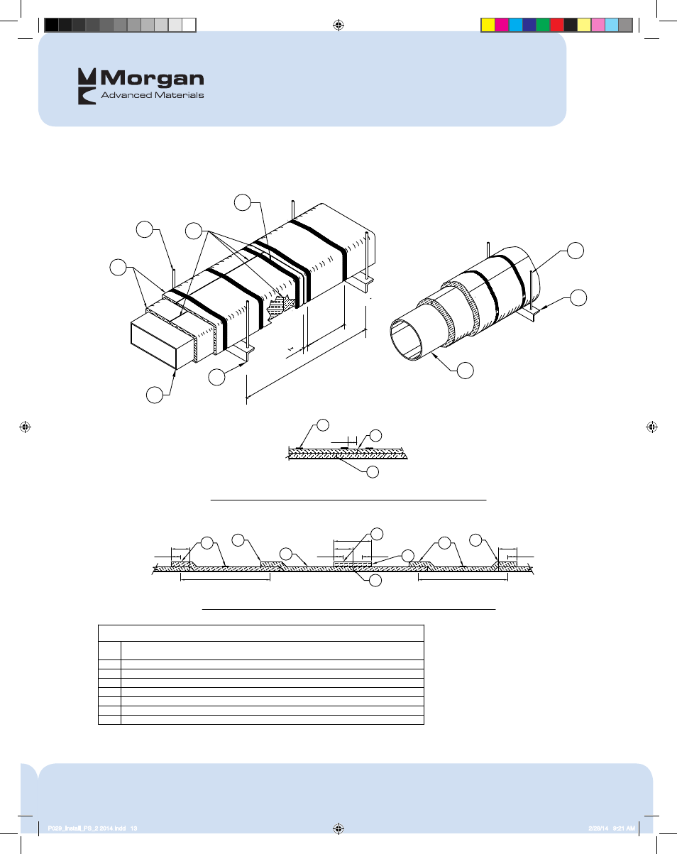
The integrity of Thermal Ceramics duct systems is limited to the quality of the installation.
Tight butt joints (no overlap) at perimeter and longitudinal joints, both layers for grease ducts
Min. 3" (75) overlap on perimeter and between adjacent blankets
Two Layers of XL Insulation for ASTM E2336 and CAN/ULC S144 Grease Duct Enclosures
LEGEND
1
4
5
3
2
Steel banding minimum 1/2" (13) wide by 0.015" (0.4) thick.
Optional 6" XL collar
6" (155)
Checkerboard Wrap Option
Telescope Wrap Option
21" (533) TYP.
Butt Joint Option
21" (533) TYP.
1 1/2" (38)
3" (75)
1 1/2" (38)
3" (75)
1 1/2" (38)
3" (75)
1 1/2" (38)
SINGLE LAYER INSTALLATION OPTIONS (2-Hour rated HVAC Duct per UL HNLJ V-19)
One Layer of XL Insulation for 2-Hour Air Ventilation Duct Enclosures
2
4
2
1
4
2
3
2
5
3
3
TWO LAYER INSTALLATION (Grease Duct per ASTM E2336 and CAN/ULC S144)
Butt Joint / Butt Joint Typical
Hangers - size dependent weight of assembly (see datasheet Section G)
Trapeze Supports - size dependent on weight of assembly (see datasheet Section G)
6
7
Steel Rectangular or Round Duct (size, gage and construction dependent per Listed Design)
8
1 1/2" (38)
6
7
8
1
2
3
7
60" (1500)
TYP.
8
1 1/2" (38)
10 1/2" (267 )O.C.
6
P029_Install_PS_2 2014.indd 13
2/28/14 9:21 AM